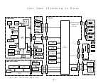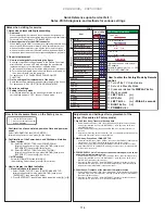
Structure of Layers in Service Factory Mode
INFORMATION mode
1. VERSION (1)
The software versions for each microcomputer
2. VERSION (2)
The Flash memory versions for each device
3. VERSION (3)
The Flash memory versions for each device
4. MAIN NG
The shutdown message ID/event times
(Going Clear mode by [ENTER/SET] key)
4-1.
CLEAR
Select Yes by [
l
] key
l
pushing and hold [ENTER/SET] key
5. TEMPERATURE
The temperature/FAN rotating status/Room Light Sensor
6. HOUR METER
The HOUR METER/P-COUNT information
6-1.
CLEAR
Select Yes by [
l
] key
l
pushing and hold [ENTER/SET] key
7. HDMI SIGNAL INFO 1
The information of HDMI information files
8. HDMI SIGNAL INFO 2
The information of HDMI information files
9. VDEC SIGNAL INFO 1
The signal information of VDEC
10. VDEC SIGNAL INFO 2
The signal information of VDEC
11. DTV TUNING STATUS 1
Detail information for DTV
12. DTV TUNING STATUS 2
Detail information for DTV
13. DTV TUNING STATUS 3
Detail information for DTV
14. DTV TV-GUIDE BER
For production line use
15. DEBUG INFO
For factory use
PANEL FACTORY mode
Refer to [PANEL FACTORY MODE]
OPTION mode
1. EDID WRITE MODE
For factory use
2. ANTENNA MODE
For production line use
3. AFT
For production line use
4. SYNC DET
For technical analysis
INITIALIZE mode
1. SIDE MASK LEVEL
For factory use
1-1. SIDE MASK LEVEL
2. FINAL SETUP
Set to Factory default settings (it should perform after
2-1. DATA RESET
replacing a MAIN Assy)
3. HMG/HG SERVICE MODE Information for a USB device is displayed
3-1.
MODE
SHIFT
4. Wide XGA AUTO
For technical analysis
Quick Reference upon Service Visit
2
Mode transition and structure of layers in Service Factory mode
INFORMATION mode
1.
VERSION
(1)
2. VERSION (2), (3)
3. MAIN NG
4.
TEMPERATURE
5. HOUR METER
6. HDMI SIGNAL INFO 1
7. HDMI SIGNAL INFO 2
8. VDEC SIGNAL INFO 1
9. VDEC SIGNAL INFO 2
10. DTV TUNING STATUS 1, 2, 3
11. DTV TV-GUIDE BER
12. DEBUG INFO
PANEL FACTORY mode
1. PANEL INFORMATION
2. PANEL WORKS
3. POWER DOWN
4. SHUT DOWN
5. PANEL-1 ADJ
6. PANEL-2 ADJ
7. PANEL FUNCTION
8. ETC.
9. RASTER MASK SETUP
10. PATTEN MASK SETUP
11. COMBI MASK SETUP
INITIALIZE mode
1. SIDE MASK LEVEL
2. FINAL SETUP
3. Wide XGA AUTO
OPTION mode
1. EDID WRITE MODE
2. ANTENNA MODE
3. AFT
4. SYNC DET
• To shift to another mode, press [MUTING].
• To shift to another item in a specific mode,
press
[
i
] or [
j
].
• To shift to the next nested layer below for an
item with a "(+)" indication, press [ENTER/SET].
To return to the next nested layer above,
also press [ENTER/SET].
Mode transition in Service Factory mode
Up
Down
Structure of Layers in Panel Factory Mode 2
7. PANEL FUNCTION (+)
1. R-LEVEL
2. G-LEVEL
3. B-LEVEL
4. ADDRESS L1
Items for use by engineers
5. ADDRESS L2
• • • • •
11. ADDRESS U4
12. STK MODE
8. ETC (+)
1. BACKUP DATA
For transferring backup data (after replacement of
the DIGITAL Assy)
2. DIGITAL EEPROM
To clear data of the digital video
3. PD INFO.
4. SD INFO.
For clearance of data for the corresponding items.
5. HR-MTR INFO.
The clearing method is the same: Select "CLEAR",
6. PM/B1-B5
using [
l
], then hold [ENTER/SET] pressed for at
7. P COUNT INFO.
least 5 seconds. After clearance is completed, {ETC}
8. MAX TEMP.
is automatically selected.
9. RASTER MASK SETUP (+)
1. MASK OFF
2. RST MASK 01
For use while Raster Mask (full mask) is displayed.
• • • • •
Use [
i
] or [
j
] to select the type of mask.
26. RST MASK 25
10. PATTEN MASK SETUP (+)
1. MASK OFF
2. PTN MASK 01
For use while Pattern Mask is displayed. Use [
i
] or
• • • • •
[
j
] to select the type of mask.
50. PTN MASK 49
11. COMBI MASK SETUP (+)
1. MASK OFF
2. CMB MASK 01
For use while Combination Mask is displayed.
• • • • •
Use [
i
] or [
j
] to select the type of mask.
18. CMB MASK 17
Structure of Layers in Panel Factory Mode 1
1. PANEL INFORMATION
Version indication of the panel
2. PANEL WORKS
Indications of the accumulated power-on time, pulse-meter
count, and power-on count of the panel
3. POWER DOWN
Indication of the Power-down history
4. SHUT DOWN
Indication of the Shutdown history
5. PANEL-1 ADJ (+)
1. VOL SUS
2. VOL OFFSET
• • • • •
8. VOL YNOFS4
9. RESET1ST_KSB
10. RESET2ND_KSB
• • • • •
23. YSTL_FMR_HZ
24. SUS FREQ
6. PANEL-2 ADJ (+)
1. R-HIGH
2. G-HIGH
3 .B-HIGH
Parameters for the WB adjustment of the panel, which are
4. R-LOW
required during adjustment after panel replacement
5. G-LOW
6. B-LOW
7. ABL
Setting of the power consumption. A setting table is
available for each vertical signal.
To "Structure of Layers in Panel Factory Mode 2"
For AM noise prevention (Depending on the mode,
brightness of the screen changes.)
For confirmation of the result of the setting change,
the unit must be turned off then back on again.
Modification not required because these items
are basically for factory presetting
Settings required after replacement of the panel
115
PDP4280HD, PDP5080HD
Summary of Contents for Elite PRO-506PU
Page 2: ......
Page 8: ... 2 4 SI PG06003 A Warranty Claim Example 8 ...
Page 14: ...14 Quick Reference G 3 to G 8 Power Down Shut Down Trap Switch Reset Service Remotes ...
Page 23: ...23 Models PDP433PU PDP503PU Block Diagrams Shut Down Power Down Diagnosis ...
Page 30: ...30 Models PDP433CMX PDP503CMX PDP4300 PRO800HD HDI PRO1000HD HDI ...
Page 31: ...31 Block Diagrams Basic Service Factory Mode Shut Down Power Down Diagnosis ...
Page 48: ...48 Models PDP434CMX PDP504CMX PDP505CMX PDP4304 PDP4314 PDP5004 PDP5014 PRO810HD PRO1010HD ...
Page 49: ...49 Block Diagrams Operation LED Statuses Power Down Shut Down Diagnosis ...
Page 72: ...72 Models PDP436PU PDP506PU PRO436PU PRO506PU ...
Page 73: ...73 Block Diagrams Operation LED Statuses Shut Down Power Down Diagnosis System Reset ...
Page 82: ...82 Models PDP4270HD PDP4271HD PDP5070HD PDP5071HD PDP6070HD PDP6071HD PRO507PU PRO607PU ...
Page 87: ...87 Models PDP6070HD PDP6071HD PRO607PU Block Diagrams on the next two pages ...
Page 120: ...120 Scan IC Troubleshooting Blue Glue Removal IC Removal ...
Page 121: ......
Page 142: ...142 ...

