PRO-1010HD
107
5
6
7
8
5
6
7
8
C
D
F
A
B
E
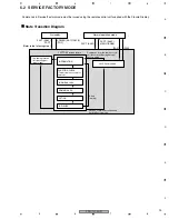
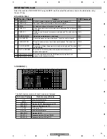
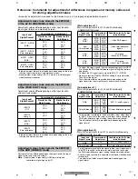
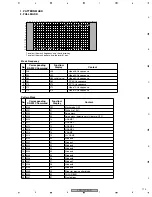
Reference: Commands for adjustment of differences in signals and memory cells used
for storing adjustment values
• Basically no adjustment is required for the Service Assy, as it is properly adjusted before shipment.
Adjustment values differ depending on the input function,
input signal format, and main/sub screen.
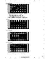
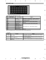
Adjustment values to be stored in the EEPROM
of the AV I/O (INDIVIDUAL mode)
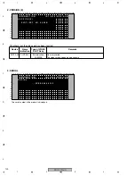
[Main adjustment 1]
Main A/D adjustments for R, G, and B individually
(COMMON-RGB mode)
Adjustment values differ depending on the signal resolution, input
signal format, and main/sub screen.
Note:
No adjustment is required for HDMI input or signals
converted to digital signals by IC1.
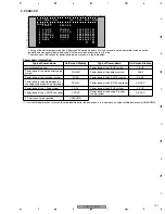
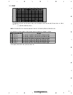
Adjustment values to be stored in the EEPROM
of the RGB (COMMON mode)
Adjustment values differ depending on the input function
and main/sub screen.
• Eight adjustment tables are provided here, depending on the input
function and main/sub screen.
• Eight adjustment tables are provided here, depending on the input
function, input signal format, and main/sub screen.
• No adjustment is required for INPUT 2, which is of HDMI (digital
video interface) standards.
• To adjust the video signals, input corresponding signals to INPUT
5 to change the RGB/color-difference signal setting then perform
adjustment.
• To adjust the PC signal, input a signal to INPUT 1 (D-SUB).
Make sure that the SIGNAL FORMAT setting is correctly made.
Then adjust the signal.
• Four adjustment tables are provided here, depending on the
signal resolution, input signal format, and main/sub screen.
• For adjustment according to the above tables, input video signals
to INPUT 5 to switch to the route for sub input and to change the
RGB/color-difference signal setting then perform adjustment.
• Two adjustment tables are provided here, depending on the
signal format.
• For adjustment according to the above tables, input video signals
to INPUT 5 to switch to the route for main input and to change
the RGB/color-difference signal setting then perform adjustment.
• A contrast gain commits this adjustment command simultaneously
three colors.
• Two adjustment tables are provided here, depending on the
signal format.
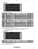
Adjustment values to be stored in the EEPROM
of the VIDEO SLOT 1 Assy
Input and
Signal Format
Commands for Adjustment
Route for the
Main Screen
Route for the
Sub Screen
INPUT3
(Y/C)
VSG
VSO
RYG
GYG
BYG
INPUT4
(Comp. V)
VSG
VSO
RYG
GYG
BYG
INPUT5
(RGB)
RYG
GYG
BYG
RYG
GYG
BYG
INPUT5
(Color difference)
RYG
GYG
BYG
RYG
GYG
BYG
Input and
Signal Format
Commands for Adjustment
Route for the
Main Screen
Route for the
Sub Screen
INPUT1 - D-SUB
(RGB)
RYG
GYG
BYG
RYG
GYG
BYG
INPUT1 - D-SUB
(Color difference)
RYG
GYG
BYG
RYG
GYG
BYG
INPUT1 - HDMI
(RGB)
RYG
GYG
BYG
RYG
GYG
BYG
INPUT1 - HDMI
(Color difference)
RYG
GYG
BYG
RYG
GYG
BYG
Input and
Signal Format
Commands for
Adjustment
Conditions for the Tables
to be Switched
480i
(RGB)
MRG
MGG
MBG
MRO
MGO
MBO
Video RGB signals
480i
(Color difference)
MRG
MGG
MBG
MRO
MGO
MBO
Video color-difference
signals
Input and
Signal Format
Commands for
Adjustment
Conditions for the Tables
to be Switched
RGB
SRG
SGG
SBG
SRO
SGO
SBO
All R, G, and B signals
Color difference
SRG
SGG
SBG
SRO
SGO
SBO
All color-difference signals
Input and
Signal Format
Commands for
Adjustment
Conditions for the Tables
to be Switched
RGB
ADC
All R, G, and B signals
Color difference
ADC
All color-difference signals
VGA
(RGB)
MRG
MGG
MBG
MRO
MGO
MBO
PC signals
(640x400 - 832x624)
XGA
(RGB)
MRG
MGG
MBG
MRO
MGO
MBO
PC signals
(1024x768 - 1280x768)
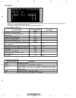
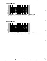
[Sub adjustment 1]
Main A/D adjustments for R, G, and B individually
(COMMON-RGB 1 mode)
[Main adjustment 2]
Main A/D adjustments for all R, G, and B simultaneously
(COMMON-RGB 2 mode)

