PRO-1010HD
147
5
6
7
8
5
6
7
8
C
D
F
A
B
E
4
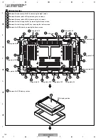
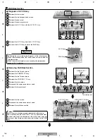
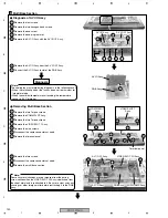
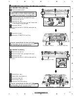
Remove the one screw.
3
Remove the one nyron rivet.
1
Remove the enclosure sheet 1.
5
Remove the LED Assy.
2
Remove the jumper wire by removing the flat clamp.
2
Remove the jumper wire by removing the flat clamp.
6
Remove the front chassis VR (50M) by removing the five
screws.
7
Remove the eight screws.
8
Remove the X CONNECTOR A and B Assy.
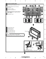
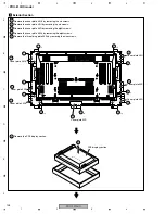
X CONNECTOR A Assy, B Assy, 50 SCAN A Assy and B Assy
3
Remove the one screw.
4
Remove the front chassis VL (50M) by removing the five
screws.
1
Remove the one nylon rivet.
6
Remove the ten screws.
5
Remove the SCAN heatsink by removing the two screws.
7
Disconnect the two pin connectors.
8
Remove the two spacers.
9
Remove the 50 SCAN A and B Assy.
4
Front chassis VR (50M)
Flat
clamp
Enclosure
sheet 1
50 X DRIVE Assy
50 Y DRIVE Assy
50 Y DRIVE Assy
50 X DRIVE Assy
LED Assy
X CONNECTOR B Assy
50 SCAN B Assy
50 SCAN A Assy
X CONNECTOR A Assy
6
6
4
4
5
5
4
3
6
6
7
8
8
6 6
6
6
4
2
6
6
6
1
2
3
4
5
7
8
7
1
9
9
8
4
×
4
×
4
×
3
×
3
7
Flat clamp
SCAN heatsink
Front chassis VL (50M)
X CONNECTOR A and B Assy
50 SCAN A and B Assy
Note:
Be sure to remove this screw. If you don't, the connector
on the LED Assy may be damaged.
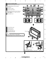
Note:
Enclosure sheet 1 is attached to comply with the safety
standards. Make sure that it will not be shifted or peeled off.
If it is peeled off, securely reattach it in its original place.
Note when reassembling the front chassis VR (50M)
Remove or loosen the screws that secure the panel holder in
order not to damage the front protect panel Assy.
Note when reassembling the front chassis VL (50M)
Remove or loosen the screws that secure the panel holder in
order not to damage the front protect panel Assy.


