background image

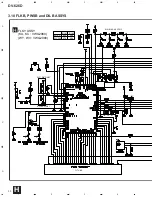
DV-626D

44

A

B

C

D

1

2

3

4

1

2

3

4

JCKB ASSY

G

SIDE B

G

Summary of Contents for DV-626D

Page 1: ...IST 52 6 ADJUSTMENT 59 CONTENTS 7 GENERAL INFORMATION 61 7 1 DIAGNOSIS 61 7 1 1 TEST MODE SCREEN DISPLAY 61 7 1 2 TROUBLE SHOOTING 63 7 1 3 ERROR CODE 64 7 1 4 DISASSEMBLY 68 7 2 PARTS 69 7 2 1 IC 69 7 2 2 DISPLAY 86 8 PANEL FACILITIES AND SPECIFICATIONS 87 T IZE AUG 1999 Printed in Japan DVD PLAYER Type Model Power Requirement Region No Remarks DV 626D KU AC120V 1 KC AC120V 1 WY AC220 240V 2 WV A...

Page 2: ... evident from visual inspection nor the protection afforded by them necessarily can be obtained by using replacement components rated for voltage wattage etc Replacement parts which have these special safety characteristics are identified in this Service Manual Electrical components having such features are identified by marking with a on the schematics and on the parts list in this Service Manual...

Page 3: ...ection switch for the inside position S201 ON and to set the loading status detection switch for the clamp position the center terminal of S301 is shorted to 5V The 650 nm laser diode for DVD oscillation will continue if pin 19 of IC1 is shorted to 5V fault condition in the DVDM assy The 780 nm laser diode for CD oscillates if pin 20 of IC1 is shorted to 5V in the DVDM assy In the test mode the la...

Page 4: ...nent parts indicates the importance of the safety factor of the part Therefore when replacing be sure to use parts of identical designation Screws adjacent to mark on the product are used for disassembly FRONT 10 21 22 18 11 KU and KC Types Only KC Type Only KC Type Only WY and WV Types Only WY Type Only KU KC and WY Types Only WV Type Only 12 13 14 15 16 3 9 4 20 1 2 18 6 7 19 23 5 8 ...

Page 5: ...ns German Italian Operating Instructions Spanish Portuguese Operating Instructions Dutch Swedish Power Cord KC Label Polyethylene Bag 0 03 200 300 Polyethylene Bag 0 03 230 340 Battery Cover Cord Holder VXX2627 Not used VHG1825 ARY7023 VRB1225 Not used Not used Not used Not used Not used ADG7021 Not used VHL1051 Not used VNK4423 Not used VXX2627 Not used VHG1825 ARY7024 VRB1225 VRC1096 Not used No...

Page 6: ...Screw BCZ40P060FZK 12 Clamper Plate VNE2068 13 Bridge VNE2069 14 Clamper VNL1738 15 Screw BPZ26P080FZK 16 Screw BBZ30P080FMC 17 65 Label See Contrast table 2 18 Caution Label See Contrast table 2 19 Screw VBA1057 20 Door Spring VBH1305 Mark No Description Part No Mark No Description Part No 2 CONTRAST TABLE DV 626D KU KC WY and WV are constructed the same except for the following Mark No Symbol an...

Page 7: ...No Symbol and Description Part No Remarks KU Type KC Type WY Type WV Type NSP 1 2 5 6 8 11 FLKY Assy PWSB Assy Front Panel FL Lens PW Button POWER LED Lens VWG2089 VWG2094 VNK4460 VEC2062 VNK4101 Not used VWG2089 VWG2094 VNK4460 VEC2062 VNK4101 Not used VWG2090 VWG2095 VNK4440 VEC2055 Not used PNW2019 VWG2090 VWG2095 VNK4440 VEC2055 Not used PNW2019 5 12 6 15 13 14 10 16 1 2 11 9 1 1 4 10 10 10 7 ...

Page 8: ...3 23 23 17 3 24 4 9 7 Refer to 2 5 LOADING MECHANISM ASSY 23 1 22 21 20 13 14 2 18 10 11 12 B B C F E C F D E D A A 23 23 27 26 30 29 6 28 23 23 16 19 5 25 WY and WV Types Only WY and WV Types Only WY and WV Types Only WY and WV Types Only To PICKUP Assy ...

Page 9: ...9 21 PCB Hinge VEC1174 NSP 22 PCB Holder PNW2100 23 Screw BBZ30P080FMC NSP 24 PC Support See Contrast table 2 NSP 25 Label VRW1629 NSP 26 PCB Spacer DEC1389 NSP 27 PCB Holder VNE2122 NSP 28 Card Spacer See Contrast table 2 29 PCB Spacer VEC2077 30 PCB Support Cushion VEC2079 2 CONTRAST TABLE DV 626D KU KC WY and WV are constructed the same except for the following Mark No Symbol and Description Pa...

Page 10: ... NSP 14 LOMB Assy VWG1886 15 Connector Assy VKP2198 LOMB CN401 LOSB CN303 16 Screw VBA1055 17 Screw Z39 019 18 Flexible Cable 08P VDA1698 LOSB CN302 SMEB CN202 19 Float Base VNL1815 20 Floating Rubber VEB1286 21 Flexible Cable 24P VDA1701 Pickup Assy DVDM CN4 22 Cushion VEB1312 LOADING MECHANISM ASSY PARTS LIST 2 5 LOADING MECHANISM ASSY 11 13 12 14 15 16 8 7 17 9 10 18 21 2 22 3 4 5 6 1 Top View ...

Page 11: ...NSP 20 Disc Table VNL1747 2 6 TRAVERSE MECHANISM ASSY S 21 Hook VNL1770 22 FFC Holder VNL1802 23 Mechanism Base VNL1806 24 FG Holder VNL1807 25 Gear A VNL1808 26 Gear B VNL1809 27 Gear C VNL1810 28 Slider VNL1811 29 Gear D VNL1814 NSP 30 Magnet VYM1024 31 Screw JFZ17P025FZK 32 Screw JGZ17P028FMC 33 Screw VBA1051 34 Magnet Holder Assy VXX2507 35 Spindle Motor Assy VXX2649 36 Carriage Motor Assy VXX...

Page 12: ...E ASIC IC601 PD3410A FLASH MEMORY IC603 VYW1646 4M DRAM IC702 MN414800CSJ 07 CLOCK GENERATOR IC21 CY2081SL 655 IC22 TC7WH74FU VIDEO FILTER F101 SPDL FTS DRIVER 4 16 SERVO DSP IC352 M56788FP VIDEO ENCODER 6ch DNR IC101 PM0023AF IC201 LC78652W 12P 1 12 13 14 15 15P CN1030 12P 8P 8P CN301 CN303 CN602 CN801 1 2 CN101 1 2 CN101 2 2 CN802 2 2 6 26 23 22 21 7 22P CN905 12 10 8 7P CN904 15P CN901 CN401 CN...

Page 13: ...01 WY WV TYPES ONLY KU KC TYPES ONLY KU KC TYPES ONLY SR IN JA903 WY WV TYPES ONLY IC901 IC902 SELECTOR IC1 TC4W53F IC2 TK15402M 29 28 6 7 1 4 23 15 19 13 21 17 1 Lt2 Rt1 Rt2 FRONT L R ch R ch CENTER JA101 2 SUB WOOFER L SURROUND COAXIAL OPTICAL AC 3 PCM DIGITAL AUDIO OUT Q8 Q9 COMPOSITE VIDEO OUT S VIDEO OUTPUT Y JA801 AV OUT JA1 JA601 PB PR ANALOG COMPONENT VIDEO OUT JA701 C C Y VIDEO R L 7 9 12...

Page 14: ... WV TYPES ONLY KU KC TYPES ONLY WY WV TYPES ONLY K FLKY ASSY KU KC VWG2089 WY WV VWG2090 H PWSB ASSY KU KC VWG2094 WY WY VWG2095 I DILB ASSY VWG2099 J Note When ordering service parts be sure to refer to EXPLODED VIEWS and PARTS LIST or PCB PARTS LIST 3 2 LOMB LOSB SMEB FGSB ASSYS and OVERALL WIRING DIAGRAM ...

Page 15: ... 60Hz WY WV AC220 240V 50 60Hz AC POWER CORD KU KC ADG7021 WY ADG1127 WV ADG7004 M WY WV TYPES ONLY PICKUP ASSY VWY1055 FGSB ASSY VWG2009 D R101 680 PC101 TLP910 O CN201 52044 0345 S201 DSG1016 CN202 VKN1212 CN302 VKN1268 SMEB ASSY VWG2048 C S301 VSK1011 CARRIAGE MOTOR ASSY VXX2650 SLIDER CN401 B2B PH K S CN303 B2B PH K S SPINDLE MOTOR ASSY VXX2649 LOSB ASSY VWG1885 B VQEB ASSY KU KC VWV1669 WY WV...

Page 16: ...E 2 4 E 2 4 E 2 4 E 2 4 E 2 4 E 2 4 E 2 4 E 2 4 E 2 4 E 2 4 E 2 4 E 2 4 E CN201 L PICKUP ASSY CN301 B CN1030 VKN1471 CN120 VKN1484 CN110 VKN1479 IC352 SPDL FTS DRIVER CN201 VKN1324 1 2 4 DVD DVD DVD CD CD CD T T T T F T T F S S F F S T F T T S S T T F F F F F F T T F 3 3 DVDM ASSY 1 4 1 4 E ...

Page 17: ... 4 E 2 4 E 2 4 E 4 4 E CD CD IC751 FOR CHECKER R1 R2 R3 R4 KU KC 10k 10k WY WV 33k 22k 10k 8 9 10 11 7 6 5 DVD DVD T F S RF SIGNAL ROUTE ROM DATA SIGNAL ROUTE FOCUS SERVO LOOP LINE TRACKING SERVO LOOP LINE SLIDER SERVO LOOP LINE F T S The power supply is shown with the marked box 1 4 E ...

Page 18: ...4 E 3 4 E 3 4 E 3 4 E 1 4 E 1 4 E 1 4 E 1 4 E 4 4 E 1 4 E 3 4 E 1 4 E 1 4 E 1 4 E 1 4 E 1 4 E 1 4 E 1 4 E 3 4 E 3 4 E 4 4 E 4 4 E 4 4 E VYW1646 TC55V1001AF8 3 TO 5 CONVERTER 5 TO 3 CONVERTER MC74VHCT541ADT MC74VHCT541DT RB521S 30 RB521S 30 X601 20MHz DSS1110 V_SEL 3 4 DVDM ASSY 2 4 2 4 E ...

Page 19: ... 8 3 4 E 2 4 E 4 4 E 3 4 E 4 4 E 1 4 E 1 4 E 1 4 E 3 4 E 1 4 E 1 4 E 3 4 E 3 4 E 1 4 E 1 4 E 1 4 E 1 4 E MN414800CSJ 07 CN101 H AUDIO SIGNAL ROUTE ROM DATA SIGNAL ROUTE The power supply is shown with the marked box DVD ENCODER 3 2 4 E ...

Page 20: ...26D 20 A B C D 1 2 3 4 1 2 3 4 E 3 4 DVDM ASSY KU KC VWS1384 WY WV VWS1393 KU KC ONLY 2 4 E 2 4 E 2 4 E 2 4 E TC74VHCT541ADT 3 5 CONVERTER 100 10 100 10 MPEG2 DECODER MITSUBISHI AV1 3 5 DVDM ASSY 3 4 3 4 E ...

Page 21: ...2 4 E 2 4 E 2 4 E 2 4 E 2 4 E 2 4 E 4 4 E 2 4 E 1 4 E 4 4 E CLOCK GENERATOR CN101 F AUDIO SIGNAL ROUTE ROM DATA SIGNAL ROUTE VIDEO SIGNAL ROUTE V Y SIGNAL ROUTE Y C SIGNAL ROUTE C R SIGNAL ROUTE R G SIGNAL ROUTE G B SIGNAL ROUTE B V Y C R G B 3 4 E ...

Page 22: ... MC74VHCT541ADT 3 TO 5 CONVERTER 3 4 E 3 4 E 2 4 E 3 4 E 3 4 E 2 4 E 2 4 E 2 4 E 1 4 E 2 4 E CN2 K CN999 G2 2 CN666 G1 2 VKN1585 AUDIO SIGNAL ROUTE VIDEO SIGNAL ROUTE V Y SIGNAL ROUTE Y C SIGNAL ROUTE C R SIGNAL ROUTE R G SIGNAL ROUTE G B SIGNAL ROUTE B V Y C G R B DIR 3 6 DVDM ASSY 4 4 4 4 E ...

Page 23: ...DV 626D 23 ...

Page 24: ...DV 626D 24 A B C D 1 2 3 4 1 2 3 4 WY WV ONLY VQEB ASSY KU KC VWV1669 WY WV VWV1711 F 6 ch DNR VIDEO ENCODER R B C V Y G F 3 7 VQEB ASSY ...

Page 25: ...802 E 3 4 ROM DATA SIGNAL ROUTE VIDEO SIGNAL ROUTE V V V Y Y C G G G B B B R R R C V Y SIGNAL ROUTE Y C SIGNAL ROUTE C R SIGNAL ROUTE R G SIGNAL ROUTE G B SIGNAL ROUTE B The power supply is shown with the marked box 18 20 19 14 17 Y C B G R 12 15 13 16 ...

Page 26: ...DV 626D 26 A B C D 1 2 3 4 1 2 3 4 G 1 2 JCKB ASSY KU KC VWV1682 WY WV VWV1681 2 2 G CN905 E 4 4 DTS DECODER IC401 96k 24 bit 6 ch DAC 3 8 JCKB ASSY 1 2 1 2 G ...

Page 27: ...DV 626D 27 A B C D 5 6 7 8 5 6 7 8 UDZS6 2B UDZS6 2B TC4W53F WY WV ONLY WY WV ONLY 2 2 G 2 2 G AUDIO SIGNAL ROUTE The power supply is shown with the marked box 1 2 G ...

Page 28: ... 2 3 4 1 2 3 4 KU KC ONLY WY WV ONLY WY WV ONLY KU KC ONLY KU KC ONLY WY WV ONLY WY WV ONLY WY WV ONLY 1 2 G CN901 E 4 4 CN1 K 1 2 G G 2 2 JCKB ASSY KU KC VWV1682 WY WV VWV1681 V V V Y Y Y C C C V Y 3 9 JCKB ASSY 2 2 2 2 G ...

Page 29: ... 8 5 6 7 8 2 2 G WY WV ONLY KU KC ONLY VIDEO SIGNAL ROUTE V V V V V V Y Y Y CB CB CR CR Y Y Y C C C C C C C C Y Y SIGNAL ROUTE Y C SIGNAL ROUTE C The power supply is shown with the marked box AUDIO SIGNAL ROUTE VIDEO AMP PB PR ...

Page 30: ...DV 626D 30 A B C D 1 2 3 4 1 2 3 4 WY WV ONLY KU KC ONLY FL TUBE R141 R143 KU KC 6 2k 36k WY WV 27k 20k S101 S106 ASG7013 FLKY ASSY KU KC VWG2089 WY WV VWG2090 H H 3 10 FLKB PWSB and DILB ASSYS ...

Page 31: ...WV VWG2095 I DILB ASSY VWG2099 J CN602 E 2 4 FLKY ASSY S101 8 PAUSE S102 7 STOP S103 FORWARD S104 41 REVERSE S105 0 OPEN CLOSE S106 3 PLAY PWSB ASSY S201 STANDBY ON POWER S202 CENTER S203 SURROUND S204 SUBWOOFER S205 5 1CH MODE S206 PICTURE CONTROL S207 VERTUAL DOLBY DIGITAL S208 AUDIO S209 FL DIMMER The power supply is shown with the marked box ...

Page 32: ...DV 626D 32 A B C D 1 2 3 4 1 2 3 4 SCRB ASSY VWV1721 WY WV ONLY K CN777 G2 2 CN904 E 4 4 CN1 VKN1243 CN2 VKN1238 V V V V V V V V Y C C C C C C C Y Y K 3 11 SCRB ASSY ...

Page 33: ...DV 626D 33 A B C D 5 6 7 8 5 6 7 8 K JA1 VKB1127 AUDIO SIGNAL ROUTE V CB SIGNAL ROUTE Y SIGNAL ROUTE C SIGNAL ROUTE V Y C V V V V V V C C C C C The power supply is shown with the marked box ...

Page 34: ...1 S S S S D BP FB C153 C154 C121 T102 T101 10 11 14 12 13 15 16 9 1 2 3 5 6 8 10 C107 C108 D151 1 2 VZF1071 R151 C151 D101 VZF1044 C103 C105 S1000 ASG1006 POWER L101 FG101 4 1 3 2 LIVE 1 2 LIVE 1 2 NEUTRAL NEUTRAL NOTE OF SPARE PARTS IN POWER SUPPLY SYPS ASSY In case of repairing use the described parts only to prevent an accident Please write the red mark on the board when the primary section of ...

Page 35: ...11 39µH 1 3A P211 VEK1041 1 0A 60V D711 VZF1065 D213 MTZJ15B D106 2 2 VZF1071 R201 47 C412 100 35 C511 47 50 C612 0 01 50 C611 0 01 50 D109 2 2 VZF1071 D151 2 2 VZF1071 IC801 AN1431T Q801 D513 MTZJ8 2B IC201 AN1431T D412 M 6V M 12V D 12V GND M 6V M 12V GND M 6V M 12V GND D 12V GND 5V GND 5V GND GND GND GND GND EV 5V P ON OFF FLAC FLAC 27V 5V 5V 5V 3 3V 3 3V 3 3V 3 3V 2 3 4 5 6 7 8 9 10 11 12 13 14...

Page 36: ...V 1V div H 5msec div 8 Foot of R261 FPWM V 1V div H 5msec div 9 Foot of R262 VPWM V 1V div H 5msec div 10 Foot of R263 PPWM V 1V div H 5msec div 11 Foot of R264 RPWM V 1V div H 5msec div 12 Q541 Base Composite Video output V 0 1V div H 10µsec div 13 Q551 Base Y output V 0 1V div H 10µsec div 14 Q531 Base C output V 0 1V div H 10µsec div Q541 Base CB output when selecting color difference output V ...

Page 37: ...n below 3 The parts mounted on this PCB include all necessary parts for several destinations For further information for respective destinations be sure to check with the schematic diagram 4 View point of PCB diagrams Symbol In PCB Diagrams Symbol In Schematic Diagrams Part Name B C E D D G G S S B C E B C E D G S B C E B C E B C E Transistor Transistor with resistor Field effect transistor Resist...

Page 38: ...811 IC25 IC54 IC801 IC21 IC22 IC807 IC806 IC903 IC261 IC302 IC101 IC601 IC761 IC352 IC603 IC606 Q112 Q112 Q102 Q281 Q601 Q602 Q111 Q107 IC702 IC610 IC303 IC31 CN201 L DVDM ASSY E CN999 G CN666 G PICKUP ASSY CN301 B CN2 K CN101 H SIDE A Q812 4 2 DVDM ASSY E This PCB is a four layered board ...

Page 39: ...905 IC803 IC805 IC27 IC802 IC201 IC701 IC231 Q543 Q179 Q106 Q542 Q105 Q237 Q113 Q114 Q101 Q103 Q251 Q106 IC608 IC701 IC701 IC904 IC609 IC299 IC612 IC751 IC792 IC791 IC604 IC607 IC611 IC73 DVDM ASSY E SIDE B CN101 F This PCB is a four layered board E ...

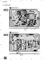
Page 40: ... B C D 1 2 3 4 1 2 3 4 VNP1696 B VNP1696 B IC102 Q551 Q541 Q531 Q521 Q511 Q501 IC103 VR102 VR101 IC106 IC1 IC105 Q502 Q512 Q522 IC104 Q532 Q542 Q552 Q1 VQEB ASSY F VQEB ASSY F SIDE B SIDE A CN802 E 4 3 VQEB ASSY F ...

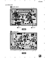
Page 41: ...DV 626D 41 A B C D 1 2 3 4 1 2 3 4 SCRB ASSY K SCRB ASSY K Q8 Q5 Q9 Q6 Q7 IC3 Q10 Q3 Q2 Q4 Q1 IC2 IC1 VNP1723 A VNP1723 A CN777 G CN904 E SIDE A SIDE B 4 4 SCRB ASSY K ...

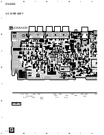
Page 42: ...DV 626D 42 A B C D 1 2 3 4 1 2 3 4 Q194 Q193 Q294 IC101 IC201 IC222 IC301 IC351 IC400 IC540 IC50 IC405 IC404 IC401 IC262 Q293 Q384 Q385 Q395 Q396 Q345 Q371 JCKB ASSY G SIDE A 4 5 JCKB ASSY G ...

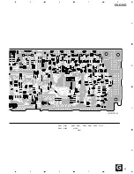
Page 43: ...DV 626D 43 A B C D 5 6 7 8 5 6 7 8 IC501 IC555 IC505 IC666 IC601 IC901 IC902 IC999 Q805 Q705 Q666 Q706 Q715 Q716 Q996 Q806 VNP1707 A CN1 K CN905 E CN901 E G ...

Page 44: ...DV 626D 44 A B C D 1 2 3 4 1 2 3 4 JCKB ASSY G SIDE B G ...

Page 45: ...DV 626D 45 A B C D 5 6 7 8 5 6 7 8 Q393 Q391 Q382 Q365 Q261 Q381 Q292 Q291 Q192 Q191 Q394 Q392 VNP1707 A G ...

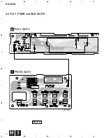
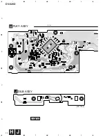
Page 46: ...DV 626D 46 A B C D 1 2 3 4 1 2 3 4 VNP1709 A FLKY ASSY H PWSB ASSY I SIDE A 4 6 FLKY PWSB and DILB ASSYS H I ...

Page 47: ...DV 626D 47 A B C D 5 6 7 8 5 6 7 8 VNP1709 A VNP1709 A IC102 IC101 Q101 DILB ASSY J CN602 E H J ...

Page 48: ...DV 626D 48 A B C D 1 2 3 4 1 2 3 4 VNP1709 A IC102 FLKY ASSY H DILB ASSY J SIDE B H J ...

Page 49: ...DV 626D 49 A B C D 5 6 7 8 5 6 7 8 VNP1709 A VNP1709 A Q102 PWSB ASSY I H I ...

Page 50: ...DV 626D 50 A B C D 1 2 3 4 1 2 3 4 POWER SUPPLY ASSY L Q104 Q101 IC151 IC801 IC201 IC411 IC311 Q102 Q103 Q801 CN110 E SIDE A AC IN LIVE NEUTRAL 4 7 POWER SUPPLY ASSY For KU and KC Types L ...

Page 51: ... A B C D 1 2 3 4 1 2 3 4 POWER SUPPLY ASSY L MSWB ASSY M Q104 Q101 IC151 IC801 IC201 IC411 IC311 Q102 Q103 Q801 CN110 E SIDE A AC IN VNP1707 A LIVE NEUTRAL 4 8 POWER SUPPLY and MSWB ASSYS For WY and WV Types M L ...

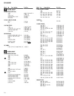
Page 52: ...istors 5 62k Ω 562 101 5621 RN1 4PC 5 6 2 1 F Mark Symbol and Description Part No Remarks KU Type KC Type WY Type WV Type NSP NSP NSP NSP NSP NSP NSP NSP NSP NSP LOAB ASSY LOMB ASSY LOSB ASSY TRAVERSE MECHANISM ASSY SMEB ASSY FGSB ASSY DVDM ASSY VQEB ASSY JCKB ASSY JCKB ASSY JCKB ASSY MSWB ASSY FLKB ASSY FLKY ASSY PWSB ASSY DILB ASSY SCRB ASSY POWER SUPPLY ASSY VWM1798 VWG1886 VWG1885 VWT1161 VWG2...

Page 53: ...sed Not used Not used Not used Not used Not used Not used Not used TC4W53F DTC124EK 2PB709A VTF1155 CKSRYB104K16 RS1 16S271J RS1 10S2701F RS1 16S103J RS1 16S3300F RS1 16S182J RS1 16S4700F RS1 16S101J RS1 16S0R0J VQEB ASSY VWV1669 and VWV1711 are constructed the same except for the following E F Mark Symbol and Description Part No Remarks VWV1682 VWV1681 S601 S801 C691 C693 C696 C812 R8 R88 R326 R3...

Page 54: ... constructed the same except for the following H I Mark No Description Part No PCB PARTS LIST FOR DV 626D KU UNLESS OTHERWISE NOTED LOMB ASSY OTHERS CN401 KR CONNECTOR B2B PH K S LOSB ASSY SWITCH S301 VSK1011 OTHERS CN303 KR CONNECTOR B2B PH K S CN302 8P FFC CONNECTOR VKN1268 CN301 12P FFC CONNECTOR VKN1272 SMEB ASSY SWITCH S201 DSG1016 OTHERS CN201 3P FFC CONNECTOR 52044 0345 CN202 8P FFC CONNECT...

Page 55: ...C24 C263 C315 C317 C332 CKSRYB104K16 C281 C354 CKSRYB222K50 C153 C266 CKSRYB223K25 C214 C251 C261 CKSRYB472K50 C357 CKSRYB473K16 C330 CKSRYB682K50 C109 C110 C120 C131 C148 CKSRYF104Z16 C150 C202 C215 C221 C222 CKSRYF104Z16 C226 C230 C235 C265 C29 CKSRYF104Z16 C31 C33 C35 C359 C367 CKSRYF104Z16 C369 C372 C402 C404 C406 CKSRYF104Z16 C408 C410 C412 C501 CKSRYF104Z16 C602 C611 C613 C616 CKSRYF104Z16 C...

Page 56: ...555 F571 F581 F591 VTF1096 F601 F901 F902 F910 VTF1096 SWITCH S601 VSH1009 CAPACITORS C669 C883 CCSQCH101J50 C508 C509 CCSQCH200J50 C107 C207 C217 CCSQCH221J50 C106 C206 C216 C327 C328 CCSQCH330J50 C337 C338 CCSQCH330J50 C101 C201 C211 C301 C311 CCSQCH331J50 C321 C322 C331 C332 CCSQCH331J50 C518 CCSQCH471J50 C340 C349 CCSQCH680J50 C103 C203 C213 CEAT100M50 C108 C113 C117 C118 C208 CEAT101M10 C218 ...

Page 57: ... C106 C114 C116 CKSQYF104Z25 C119 C120 C170 CKSQYF104Z25 RESISTORS All Resistors RS1 10S J OTHERS CN103 FJ CONNECTOR 4P 04R FJ CN102 FJ CONNECTOR 6P 06R FJ IR101 REMOTE RECEIVER UNIT GP1U28X V101 FL TUBE VAW1050 SPACER VEC1599 CN101 15P FFC CONNECTOR VKN1275 FL HOLDER VNF1087 X101 CERAMIC RESONATOR VSS1142 5MHz PWSB ASSY SWITCHES S201 S209 ASG7013 RESISTORS All Resistors RS1 10S J OTHERS CN201 FJ ...

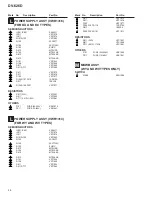
Page 58: ...3Ω VZC1057 R611 VZC1060 R711 0 51Ω 1 2W VZC1061 OTHERS F101 FUSE 2A 125V REK1078 P211 FUSE 1A 60V VEK1041 POWER SUPPLY ASSY VWR1314 FOR WY AND WV TYPES SEMICONDUCTORS IC201 IC801 AN1431T IC311 VZF1078 IC411 VZF1074 Q101 Q103 VZF1062 Q102 2SC3377 Q104 2SC1740S D102 EG01C D213 MTZJ15B D104 MTZJ2 4B D812 MTZJ6 8B D513 MTZJ8 2B D101 VZF1044 D108 VZF1045 D811 VZF1054 D211 D711 VZF1065 D411 VZF1075 D311...

Page 59: ...Note When the Traverse mechanism adjustment is prnot operly adjusted jitter error rate and play ability are defective The noise may come out by the case Master Clock Adjustment 1 6 2 JIGS AND MEASURING INSTRUMENTS EXCHANGE PCB ASSY Mechanical point Electric point Exchange board DVDM ASSY Note is adjusted already Mechanical point Electric point Exchange board JCKB ASSY 6 3 NECESSARY ADJUSTMENT POIN...

Page 60: ...V 626D Normal mode Power ON Frequency counter Player START VC21 DVDM ASSY 33 868800MHz 160Hz DVDM ASSY IC21 Pin 5 6 4 ELECTRICAL ADJUSTMENT 1 Master Clock Adjustment When not properly adjusted Uneven color ...

Page 61: ...on Output video system and Skirt terminal output FL controller version and region setting for the player Port No of Flash ROM and system controller System controller revision Flash ROM version and Flash ROM size FL controller destination setting AV1 chip version DVD mechanism controller revision Control and part No of GUI ROM Character in bold Item name Information display First Screen Display Scr...

Page 62: ...e jitter value 16 Version of the AV 1 chip AV 17 1 Version of the FL controller FL 2 Region setting of the player REG Setting value 1 to 6 18 Destination setting of the FL controller MDL For charactors in front represent the type of model There charactors that follow represent the destination code J J K KU KC KU KC R RAM RL RD LB WY WY 19 The part number of the flash ROM and system controller 1 Pa...

Page 63: ...n LOSB Assy and DVDM Assy 12P flexible cable Check the 6V power supply voltage above micro fuse FL indication is dark or flickers No Indicates the error message Refer to the section 7 1 3 ERROR CODE Refer to the section 7 1 3 ERROR CODE Check the connection between VQEB Assy and DVDM Assy Check the connection between JCKB Assy and DVDM Assy Indicate the error message A video isn t displayed Check ...

Page 64: ...t i d n a s d n o c e s D C V y b s d n o c e s 7 n i h t i w a e r a t e g r a t n a c s s p o t S D C n o i t a r e p o s e u n i t n o C D V D 2 1 y r t e r h c r a e S r o r r e 3 r e t f a d e t e l p m o c e b t o n d l u o c h c r a e s A 4 d e t u c e x e s a w p u k c a b h c r a e s s e i r t e r 6 t u o e m i t f o e s a c a n i r o s e m i t 1 1 g n i c a r t s a w t i n u e h t e l i ...

Page 65: ... t u o e m i t e h t r e t f a S m 0 5 n i h t i w n r u t e r t o n d i d Y S U B A t n e s s a w d n a m m o c g n i r u s a e m C G A y a l p N O M U S G p o t S 5 5 e c n e u q e s o t u A e p y t c s i d f o t u o e m i t g n i s n e s e h t r e t f a s d n o c e s 2 n i h t i w n r u t e r t o n d i d Y S U B A t n e s s a w d n a m m o c g n i s n e s c s i d T R S J D p o t S 6 5 e c n e u...

Page 66: ... n a m m o c e t i r w s u o u n i t n o c a r e t f a d n a e r o f e b P S D o t d e u s s i s a w n o i t a r e p o o N 1 B r o f r o r r e t u o e m i T p u k c a b 1 r o f d a e r e b t o n d l u o c s e d o c e c n e u q e s p u k c a b e h t g n i r u d e t a t s g n i c a r t e h t n I e r o m r o d n o c e s e b t o n d l u o c P S D o v r e s e h t f o e c n e u q e s N O g n i k c a r t...

Page 67: ...L P S I D Y A L P S I D C S E y a l p s i d o T L F r o r r E f o n o i t p i r c s e D D V D a h t i w f i s e s u a C D C a h t i w f i s e s u a C t i n U e h t f o n o i t a r e p O c t e 8 0 1 3 t i b r o r r e s s e c c a 1 V A G N e t i r w d a e r g n i g g u b e d s e m o c e b t i r o n o i t a r e p o o N N O o t e l b a s i r e w o p e h t f i n o i t a c i d n i c t e 4 0 1 2 t i b r ...

Page 68: ...n diagnosing the circuit under the VQEB ASSY of DVDM ASSY There is no hindrance in other actuation though the picture stops appearing when VQEB ASSY is removed When diagnosing the DVDM ASSY and VQEB ASSY use the following Flexible Cable for service DVDM CN905 JCKB CN666 Flexible Cable 29P VDA1752 DVDM CN901 JCKB CN999 Flexible Cable 15P VDA1751 DVDM ASSY SCRB ASSY MY MV types only DVDM ASSY 15 VQE...

Page 69: ...i f n o C 2 D N G d n u o r G 3 N I L A T X l a n r e t x e f o t u p n i l a t s y r c e c n e r e f e R t u p n i k c o l c e c n e r e f e r 4 T U O L A T X k c a b d e e f l a t s y r c e c n e r e f e R 5 B K L C t u p t u o k c o l c e l b a r u g i f n o C 6 C K L C t u p t u o k c o l c e l b a r u g i f n o C 7 D D V y l p p u s e g a t l o V 8 S F D P E O D N E P S U S H G I H e v i t c ...

Page 70: ... P S A D S C X O r e d o c e d S T D n i t l i u b P S D o i d u a c i g o l o r P 3 C A y b l o D 2 1 9 S S Y l e l l a r a p l a i r e S T F 5 9 5 C H V 4 7 C T r o s s e c o r p o i d u a D 3 3 5 8 1 D A h c M r o f C A D F A 7 4 8 5 M S P S A D 2 2 9 S S Y 3 2 2 G T R O P 2 F D S C X 1 T S R F D N O _ C I M X O r e d o c e d S T D n i t l i u b P S D o i d u a c i g o l o r P 3 C A y b l o D 2...

Page 71: ...F O G A O C I F R f o t u p t u o l a n g i s g n i h c t i w s F F O N O C G A 9 5 3 D T R O P X 2 D C X O k c a b y a l p d e e p s e l b u o d e h t g n i h c t i w s r o f t u p t u o l a n g i S 0 6 4 D T R O P G C I E O O t u p t u o l a n g i s g n i h c t i w s n i a g C I E O 1 6 D N G D N G D N G 2 6 5 D T R O P N O M X O r o t o m e l d n i p s e h t f o t u p t u o g n i h c t i w s F ...

Page 72: ...6 Q R I X 4 1 B P 1 1 L Q R I X I P I H C Y M 2 t u p n i t p u r r e t n I 7 0 1 7 Q R I X 5 1 B P 0 T N I X 0 Q R I V A X I 1 V A 0 t u p n i t p u r r e t n I 8 0 1 0 A C O I T 4 S C X 0 A P 4 S C X O t u p t u o l a n g i s t c e l e s p i h c P S D o v r e S 9 0 1 S A R X 5 S C X 1 A P C N O n o i t c e n n o c n o N 0 1 1 0 B C O I T 6 S C X 2 A P 6 S C X O t u p t u o l a n g i s t c e l e ...

Page 73: ... 4 A O 4 s u b s s e r d d A 2 5 1 5 A 5 A O 5 s u b s s e r d d A 3 5 1 6 A 6 A O 6 s u b s s e r d d A 4 5 1 7 A 7 A O 7 s u b s s e r d d A 5 5 1 8 A 8 A O 8 s u b s s e r d d A 6 5 1 9 A 9 A O 9 s u b s s e r d d A 7 5 1 0 1 A 0 1 A O 0 1 s u b s s e r d d A 8 5 1 1 1 A 1 1 A O 1 1 s u b s s e r d d A 9 5 1 2 1 A 2 1 A O 2 1 s u b s s e r d d A 0 6 1 3 1 A 3 1 A O 3 1 s u b s s e r d d A 1 6 1...

Page 74: ... n o N 8 3 4 Q D O I s t u p t u o s t u p n i a t a D 5 1 Y B Y R O t u p t u o y s u B y d a e R 9 3 2 1 Q D 6 1 8 1 A I s t u p n i s s e r d d A 0 4 5 Q D 7 1 7 1 A 1 4 3 1 Q D 8 1 7 A 2 4 6 Q D 9 1 6 A 3 4 4 1 Q D 0 2 5 A 4 4 7 Q D 1 2 4 A 5 4 1 A 5 1 Q D O I t u p n i s s e r d d A s t u p t u o s t u p n i a t a D 2 2 3 A 6 4 S S V d n u o r G 3 2 2 A 7 4 E T Y B I e d o m t i b 6 1 r o t i...

Page 75: ... D D V I y l p p u s r e w o P 8 2 R T N I O e h t o t t s n i a g a l a n g i s t s e u q e r t p u r r e t n I P F 3 7 7 5 6 M m o r f U P C l a n r e t x e 9 5 D H O I t r o p t u p t u o d n a t u p n i a t a D 9 2 D N G I d n u o r G 0 1 6 D H 0 3 0 A H I t r o p t u p n i s s e r d d A 1 1 7 D H 1 3 1 A H 2 1 8 D H 2 3 2 A H 3 1 9 D H 3 3 3 A H 4 1 D N G I d n u o r G 4 3 4 A H 5 1 0 1 D H O...

Page 76: ... D P 7 5 1 D N G A I d n u o r g g o l a n A 9 9 D N G I d n u o r G 8 5 3 D N G A 0 0 1 3 D P O a t a d l e x i p l a t i g i D 9 5 3 D D V A I y l p p u s r e w o p g o l a n A 1 0 1 2 D P 0 6 P A C C I d n u o r g o t t c e n n o C 2 0 1 1 D P 1 6 2 D N G A I d n u o r g g o l a n A 3 0 1 0 D P 2 6 2 D D V A I y l p p u s r e w o p g o l a n A 4 0 1 D D V I y l p p u s r e w o P 3 6 O K L C A n...

Page 77: ...D S f o e n i l l o r t n o c E W 4 4 1 2 A M N O M A R D h t i w e n i l s s e r d d A 6 8 1 U M Q D O M A R D S f o e n i l l o r t n o c M Q D t u p t u o e t y b r e p p u f o k s a m r o f e s U 5 4 1 5 A M N 7 8 1 L M Q D O M A R D S f o e n i l l o r t n o c M Q D t u p t u o e t y b r e w o l f o k s a m r o f e s U 6 4 1 3 A M N 8 8 1 D D V I y l p p u s r e w o P 7 4 1 4 A M N 9 8 1 7 D ...

Page 78: ... m e t s y S 0 1 E D O M X I t u p n i t e s e R 1 1 K C O V A I t u p n i k c o l c e c n a d i o v a k c o l r o r r e L L P 2 1 1 T S E T I n o i t a r e p o l a m r o n n i d n u o r g o t d e t c e n n o c e b t s u M t u p n i t s e T 3 1 2 T S E T I n o i t a r e p o l a m r o n n i d n u o r g o t d e t c e n n o c e b t s u M t u p n i t s e T 4 1 L C K L C S I t u p n i k c o l c e c a f...

Page 79: ...83 68 67 69 CSB 65 24 24 Main DSP AC 3 Pro Logic DTS Decoder RAM for Delay PLL Calculation Clock 30MHz STREAM0 7 L R 24 16 Sub DSP Coefficient Program RAM SDIB CKSEL SDOB CKSEL SI SCK 32 39 72 79 99 92 SDWCK0 82 SDIA0 84 SDIA1 85 SURENC 56 8 9 19 KARAOKE 55 MUTE 54 CRC 53 AC3DATA XI XO CPO 24 SDOA0 23 SDOA1 22 SDOA2 5 SDIB0 6 SDIB1 7 SDIB2 12 SDIB3 2 RAMCEN 88 RAMWEN 89 RAMOEN 15 OVFB 18 SDOB3 45 ...

Page 80: ... y l p p u s r e w o p V 3 3 2 2 2 A O D S O t u p t u o E F L C P S D n i a M m o r f n i p t u p t u o M C P 3 2 1 A O D S O t u p t u o S R S L P S D n i a M m o r f n i p t u p t u o M C P 4 2 0 A O D S O t u p t u o R L P S D n i a M m o r f n i p t u p t u o M C P 5 2 4 1 A M A R O M A R S l a n r e t x e r o f 4 1 n i p s s e r d d A 6 2 3 1 A M A R O M A R S l a n r e t x e r o f 3 1 n i p...

Page 81: ... p m o c o r c i M 0 7 2 A M A R O M A R S l a n r e t x e r o f 2 n i p s s e r d d A 1 7 1 D D V k c o l b l a n i m r e t e h t r o f y l p p u s r e w o p V 5 2 7 0 D M A R O I d e s u t o n s i M A R S l a n r e t x e n e h w t u p t u o 0 M A E R T S M A R S l a n r e t x e r o f n i p a t a D 3 7 1 D M A R 4 7 2 D M A R 5 7 3 D M A R 6 7 4 D M A R 7 7 5 D M A R 8 7 6 D M A R 9 7 7 D M A R 0...

Page 82: ...S 6 1 N R S I t u p n i t t i m h c S t e s e r L t u p n i t e s e r m e t s y S 7 1 T S E T I D N G o t t c e n n o C t u p n i l o r t n c e d o m t s e T 8 1 0 S _ C C V V 3 3 o t t c e n n o C y l p p u s r e w o P 9 1 0 S _ D N G V 0 e g a t l o v e c n e r e f e r o t t c e n n o C d n u o r G 0 2 I X I 3 2 n i p K L C g n i s u n e h w V 3 3 C C V o t t c e n n o C z H M 7 2 r o t a n o s ...

Page 83: ... 4 5 0 D M 7 4 6 0 D M 8 4 7 0 D M 9 4 4 0 _ D D V V 3 3 o t t c e n n o C y l p p u s r e w o P 0 5 5 1 D M O I B S M p u l l u p h t i w y r o m e m l a n r e t x e r o f t u p t u o d n a t u p n i a t a D 1 5 4 1 D M O I p u l l u p h t i w y r o m e m l a n r e t x e r o f t u p t u o d n a t u p n i a t a D 2 5 3 1 D M 3 5 2 1 D M 4 5 1 S _ C C V V 3 3 o t t c e n n o C y l p p u s r e w o P...

Page 84: ...t a D 7 9 1 O D 8 9 2 O D 9 9 3 O D 0 0 1 4 O D 1 0 1 5 O D 2 0 1 6 O D 3 0 1 7 O D 4 0 1 8 O D 5 0 1 9 O D 6 0 1 0 O M R O t u p t u o r o t i n o m r e t s i g e R 7 0 1 1 O M R 8 0 1 8 0 _ D D V V 3 3 o t t c e n n o C y l p p u s r e w o P 9 0 1 2 O M R O t u p t u o r o t i n o m r e t s i g e R 0 1 1 3 O M R 1 1 1 9 0 _ D D V V 3 3 o t t c e n n o C y l p p u s r e w o P 2 1 1 1 1 _ D N G V ...

Page 85: ... 0 3 1 1 B _ O A D A 0 3 3 a t c e n n o C t u p t u o t n e r r u C l e n n a h c 1 B f o t u p t u o C A D Ω D N G o t r o t s i s e r 1 3 1 1 B _ A D D D V A V 3 3 o t t c e n n o C C A D l e n n a h c 1 B r o f y l p p u s r e w o P 2 3 1 B _ U M C A 1 0 a t c e n n o C C A D _ B _ p u o r G r o f r o t i c a p a c n o i t a s n e p m o c e s a h p a t c e n n o C µ D N G o t r o t i c a p a c...

Page 86: ...S14 GUIDE TITLE S1 S2 S3 S4 S5 S6 S7 S8 S9 S10 S11 S12 S13 S14 S1 S2 S3 S4 S5 S6 S7 S8 S9 S10 S11 S12 S13 S14 S1 S2 S3 S4 S5 S6 S7 S8 S9 S10 S11 S12 S13 S14 S1 S2 S3 S4 S5 S6 S7 S8 S9 S10 S11 S12 S13 S14 S1 S2 S3 S4 S5 S6 S7 S8 S9 S10 S11 S12 S13 S14 S1 S2 S3 S4 S5 S6 S7 S8 S9 S10 S11 S12 S13 S14 S1 S2 S3 S4 S5 S6 S7 S8 S9 S10 S11 S12 S13 S14 L C R LFE S Ls Rs GUI 192kHz dts S1 S2 S3 S4 S5 S6 S7 S...

Page 87: ... to set the default audio output in the Setup screen Audio 2 menu 6 DNR indicator Indicates that the digital noise reduction function is on 7 VIRTUAL DOLBY DIGITAL indicator Indicates that the Virtual Dolby Digital function is on 8 FL OFF indicator Indicates that the player s display window has been turned off using FL DIMMER 9 Display window Displays system information 0 Remote sensor Point the r...

Page 88: ...tracks available on a DVD 1 STANDBY indicator Indicates that the player is in standby using a minimum amount of power to maintain system settings 2 CENTER button Press to turn the center speaker channel on and off when listening to sources being output from the 5 1 channel discrete audio outputs 3 SURROUND button Press to turn the surround rear speaker channels on and off when listening to sources...

Page 89: ...ress and hold to perform reverse playback scanning Disc illumination Lights when a DVD is loaded and when no disc is loaded Turns off when a disc format other than DVD is loaded in the player Disc tray When loading a disc place discs in the disc tray with the label side facing up FL DIMMER button Press to change the brightness of the FL display and disc illumination in four steps maximum brightnes...

Page 90: ...cting the player to your TV or monitor via the S video jack When using this output be sure to set VIDEO OUT SELECT to the left position 6 COMPONENT VIDEO OUT jacks If your projection monitor projector or similar component has component video inputs you can produce a higher quality picture on your projection monitor or projector by connecting to the component video outputs on this unit When using t...

Page 91: ...T jacks If your TV or monitor has an S video input clear picture reproduction is possible by connecting the player to your TV or monitor via the S video jack 5 AUDIO OUT 2 ch jacks Use to output two channel audio analog to the audio stereo inputs on a TV or stereo amplifier If you are connecting to a receiver that has both digital and analog input jacks for DVD player connection it may be benefici...

Page 92: ...r stop mode to open and close the Setup screen 6 MULTI DIAL Use to control the rate of forward or reverse playback in Jog Mode 7 Light button side panel Use to illuminate the main operation buttons on the remote control When pressed the buttons light for approximately 3 seconds This function is convenient for locating the command buttons when the room is dark 8 VIDEO ADJUST V ADJ button Various at...

Page 93: ...sor control joystick or to set items highlighted in a menu DIMMER FL button Press to change the brightness of the FL display and disc illumination in four steps maximum brightness medium brightness minimum brightness and off When the FL display is turned off the FL OFF indicator on the front panel lights _ JOG MODE indicator Lights red when the player is in the Jog Mode JOG MODE JOG button Press t...

Page 94: ...se to display or close the DVD menu screen 5 TOP MENU button Press to call up the top menu programmed on the DVD Depending on the DVD the top menu may be identical to the DVD menu 6 PREVIOUS 4 NEXT buttons During playback press PREVIOUS 4 to go back to a previous chapter track and NEXT to advance to the next chapter track 7 REV 1 FWD fast reverse forward buttons During playback of DVD and Video CD...

Page 95: ...ay different information RETURN button Use to go one menu back current settings are maintained Use RETURN when you do not want to change the option setting in a menu Cursor buttons 2 3 5 Use to move through the options on menu screens and to change settings ENTER button Use to implement settings selected with the cursor buttons or to set items highlighted in a menu PLAY 3 button Press to start dis...

Page 96: ...LAY has been pressed 0 DTS indicator Indicates DTS audio playback DOLBY DIGITAL indicator Indicates Dolby Digital audio playback REMAIN indicator Indicates that the remaining playback time of a title or chapter track is being displayed Counter display Displays the playback mode type of disc title and chapter track numbers playback time etc LFE channel indicator The LFE low frequency effects channe...

Page 97: ...A jack Component video output Y PB PR Output level Y 1 0 Vp p 75 Ω PB PR 0 7 Vp p 75 Ω Jacks RCA jack Audio output 2 pairs Output level During audio output 200 mVrms 1 kHz 20 dB Number of channels 2 Jacks RCA jack Audio output 5 1 CH Output level During audio output 200 mVrms 1 kHz 20 dB Number of channels 6 Jacks RCA jack Digital audio characteristics Frequency response 4 Hz to 44 kHz DVD fs 96 k...

Page 98: ...output 200 mVrms 1 kHz 20 dB Number of channels 6 Jacks RCA jack Digital audio characteristics Frequency response 4 Hz to 44 kHz DVD fs 96 kHz S N ratio more than 115 dB Dynamic range more than 103 dB Total harmonic distortion 0 002 Wow and flutter Limit of measurement 0 001 W PEAK or lower Digital output Optical digital output Optical digital jack Coaxial digital output RCA jack Other terminals C...

Reviews: