117
C-AX10
ANALOG INPUT
1
-
=
!
~
2 3 4 5
6
7
8 9 0
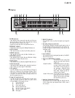
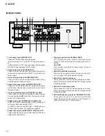
Display
1
OVER indicator
This indicator turns on when the input level of the ana-
logue signal is too high or when the signal level during
the internal DSP operation is too high.
Adjust the input gain when this indicator turns on.
2
MIDNIGHT indicator
This indicator turns on when the Midnight function is on.
3
Hi-bit indicator
This indicator turns on when the Hi-bit function is on.
4
DIRECT indicator
This indicator turns on when the Direct function is on.
5
NETWORK indicator
This indicator turns on when the amplifier is set to Digi-
tal Network (Channel Divider) mode.
6
DNR indicator
This indicator turns on when the digital NR function is on.
7
Character display
This display shows alphanumeric characters and sym-
bols to convey various types of information.
8
LFE indicator
The LFE indicator turns on when LFEs (low frequency
effect) are contained in the playback software. When
LFE signals are actually played back (LFE signals do
not exist in the entire sound track), the
÷
mark next to
the LFE indicator turns on.
9
Program Format indicator
The channel indicators corresponding to the input sig-
nals turn on when a PDIF connection is made or when
a Dolby Digital or DTS signal is input.
L:
Front left channel
C:
Centre channel
R:
Front right channel
LS:
Surround left channel
S:
Surround channel (monaural)
RS:
Surround right channel
LFE: LFE signal
0
UNLOCK indicator
This indicator turns on when the digital input signal is
cut off.
-
Sampling Frequency indicator
This indicator displays the sampling frequency (fs) of
the digital REC OUT signal selected in the section “Se-
lecting the Digital Output Sampling Frequency during
Analogue Input”.
96 : 96 kHz
48 : 48 kHz
=
Input indicator
The indicator for the input signal selected by the INPUT
SELECTOR turns on.
~
2
Surround/DTS Mode indicator
DTS:
This indicator turns on when DTS
signals are input while
Ÿ
/DTS
mode is on.
DOLBY DIGITAL:
This indicator turns on when play-
ing back Dolby digital signals
while Dolby Surround/ mode is
o n . H o w e v e r , D O L B Y P R O
LOGIC turns on when playing
back Dolby Digital signals re-
corded in two channels.
DOLBY PRO LOGIC: This indicator turns on when play-
ing back a two-channel source in
DOLBY PRO LOGIC while Dolby
Surround/DTS button is on.
!
DIGITAL INTERFACE indicator
This indicator turns on when using the INPUT SELEC-
TOR to choose the input signals when a PDIF connec-
tion is made.
Summary of Contents for C-AX10
Page 9: ...9 C AX10 ...
Page 13: ...C AX10 13 A B C D 1 2 3 4 1 2 3 4 E FRAD ASSY F CRAD ASSY 24 576MHz 24 576MHz 3 1 3 A D BLOCK ...
Page 14: ...C AX10 14 A B C D 1 2 3 4 1 2 3 4 H AUDIO A ASSY 3 1 4 D A BLOCK AUDIO A ASSY ...
Page 15: ...C AX10 15 A B C D 1 2 3 4 1 2 3 4 I AUDIO B ASSY 3 1 5 D A BLOCK AUDIO B ASSY ...
Page 16: ...C AX10 16 A B C D 1 2 3 4 1 2 3 4 A DIGITAL I O ASSY B DSP ASSY 3 1 6 DIGITAL SIGNAL BLOCK ...
Page 17: ...C AX10 17 A B C D 5 6 7 8 5 6 7 8 to D A SECTION Hi bit Hi bit Hi bit ...
Page 18: ...C AX10 18 A B C D 1 2 3 4 1 2 3 4 A E F Hi bit Hi bit Hi bit FRONT 3 1 7 µ COM PORT BLOCK ...
Page 35: ...C AX10 35 A B C D 5 6 7 8 5 6 7 8 AUDIO SIGNAL ROUTE 9 3 3V 3 3V x2 1 10W 3 6 G ...
Page 37: ...C AX10 37 A B C D 5 6 7 8 5 6 7 8 AUDIO SIGNAL ROUTE G1 6 11 11 4 6 G ...
Page 39: ...C AX10 39 A B C D 5 6 7 8 5 6 7 8 G1 6 5 6 G ...
Page 66: ...C AX10 66 A B C D 1 2 3 4 1 2 3 4 AUDIO A ASSY H SIDE B Q910 Q912 Q908 Q902 Q901 Q907 Q903 H ...
Page 67: ...C AX10 67 A B C D 5 6 7 8 5 6 7 8 Q901 Q905 Q906 Q904 907 Q903 ANP7291 D H ...
Page 71: ...C AX10 71 A B C D 5 6 7 8 5 6 7 8 Q1003 Q1007 Q1001 Q1005 Q1006 Q1004 Q1009 ANP7291 D I ...

