115
C-AX10
DIGITAL CONTROL AMPLIFIER
REMOTE CONTROL UNIT CU-005
SOUND MEMORY
DIGITAL
INPUT
ANALOG
INPUT
TONE CONTROL
BALANCE
NETWORK
L
R
ENTER
SETUP
ALL
SYSTEM
CHECK
TEST
TONE
INPUT
GAIN
REMOTE
ON/OFF
DIGITAL
NR
DIRECT
Hi-bit
MEMO
MID-
NIGHT
FRONT
MUTING
CH SELECT
DIMMER
2ch/
multi ch
CH LEVEL
VOLUME
CENTER
SURR.
1
A
M1
M2
M3
M4
M5
M6
M7
M8
B
C
2
3
4
5
6
1
DVD
2
3
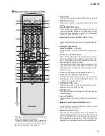
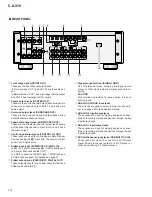
Remote Control Unit (CU-C005)
This figure shows the remote control when the
slide cover has been pulled down.
To open the slide cover, press on the
fi
mark on the
cover and the indentation on the back of the remote
control, and then pull the cover down slightly so that
the lock releases with a clicking sound.
1
Hi-bit button
This button is used to turn the Hi-bit function on and off.
2
DIGITAL NR button
This button is used to select the Digital NR function
mode.
3
SOUND MEMORY buttons
These buttons are used to save and recall up to 16
tone control setting patterns and 8 speaker setup pat-
terns. The three buttons A, B, and C can be selected
within the eight buttons M1 to M8.
4
Digital Input selector (DIGITAL INPUT 1 to 6)
These buttons are used to select the digital input sig-
nal.
5
Analogue Input selector
(ANALOG INPUT 1 to 3, DVD)
These buttons are used to select the analogue input
signal.
6
2ch/multi ch (
2
/DTS) button
When DVD-A input is selected, this button is used to
select two-channel input, multichannel (six channel) in-
put, or multichannel output after conversion of the two-
channel signal to Dolby Pro Logic.
If an input other than DVD-A input is selected, OFF
(2ch) and ON (multi) for Dolby Digital, Dolby Pro Logic,
DTS, and Surround Mode are set according to the sig-
nal that is input.
7
Channel Level buttons (CHANNEL LEVEL +, –)
8
Channel Select buttons (CH SELECT)
To adjust the channel level, use this button to choose
the channel, and then use the CHANNEL LEVEL + and
– buttons (
7
) to adjust the level.
9
SYSTEM SET UP button
This button is used to enter System Setup mode for
speaker setup or selecting modes.
0
CHECK button
This button is used to enter the mode for checking the
current settings.
-
2
/
3
/
5
/
∞
buttons
These buttons are used to make selections and set-
tings.
=
Balance Control buttons (BALANCE L, R)
These buttons are used to adjust the balance of the
front left and right channels.
~
REMOTE ON/OFF button
This button is used to select whether the amplifier can
receive operations from the remote control (ON) or not
(OFF). Set to OFF when more than one Pioneer ampli-
fier is operating at the same time. When set to OFF, the
amplifier can be operated only from the amplifier unit.
Summary of Contents for C-AX10
Page 9: ...9 C AX10 ...
Page 13: ...C AX10 13 A B C D 1 2 3 4 1 2 3 4 E FRAD ASSY F CRAD ASSY 24 576MHz 24 576MHz 3 1 3 A D BLOCK ...
Page 14: ...C AX10 14 A B C D 1 2 3 4 1 2 3 4 H AUDIO A ASSY 3 1 4 D A BLOCK AUDIO A ASSY ...
Page 15: ...C AX10 15 A B C D 1 2 3 4 1 2 3 4 I AUDIO B ASSY 3 1 5 D A BLOCK AUDIO B ASSY ...
Page 16: ...C AX10 16 A B C D 1 2 3 4 1 2 3 4 A DIGITAL I O ASSY B DSP ASSY 3 1 6 DIGITAL SIGNAL BLOCK ...
Page 17: ...C AX10 17 A B C D 5 6 7 8 5 6 7 8 to D A SECTION Hi bit Hi bit Hi bit ...
Page 18: ...C AX10 18 A B C D 1 2 3 4 1 2 3 4 A E F Hi bit Hi bit Hi bit FRONT 3 1 7 µ COM PORT BLOCK ...
Page 35: ...C AX10 35 A B C D 5 6 7 8 5 6 7 8 AUDIO SIGNAL ROUTE 9 3 3V 3 3V x2 1 10W 3 6 G ...
Page 37: ...C AX10 37 A B C D 5 6 7 8 5 6 7 8 AUDIO SIGNAL ROUTE G1 6 11 11 4 6 G ...
Page 39: ...C AX10 39 A B C D 5 6 7 8 5 6 7 8 G1 6 5 6 G ...
Page 66: ...C AX10 66 A B C D 1 2 3 4 1 2 3 4 AUDIO A ASSY H SIDE B Q910 Q912 Q908 Q902 Q901 Q907 Q903 H ...
Page 67: ...C AX10 67 A B C D 5 6 7 8 5 6 7 8 Q901 Q905 Q906 Q904 907 Q903 ANP7291 D H ...
Page 71: ...C AX10 71 A B C D 5 6 7 8 5 6 7 8 Q1003 Q1007 Q1001 Q1005 Q1006 Q1004 Q1009 ANP7291 D I ...


