133
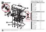
AVX-P7300DVD
During horizontal operation: 68msec.
When start-up operation: 191msec.
1
2
3
4
5
6
7
8
9
10
11
12
13
Counting of edges
Phase difference: 90º degrees
For forward rotation
DEGPUL1
DEGPUL2
Angular pulse
200
µ
sec
-
DISPLAY SECTION MECHANICAL OPERATION
SPECIFICATION
-
Direction of rotation
Forward rotation (ejection):
The phase of DEGPUL1 advances by 90 degrees.
Reverse rotation (retraction)
The phase of DEGPUL1 loses by 90 degrees.
-
Cautions
1. The angular position is continuously incremented,
with the last position stored in the memory for use
when the system is turned on again.
However, when the display is forcibly moved by the
hand etc. ,the position is not memorized.
2. If a specified pulse is not detected during an
operation, it is determined that an operational
abnormality exists, and the operation will be halted
at that point.
3. The brake operation is performed at 14ms + 200ms
(
←
time required for monitoring the chattering) after
the prescribed L angular pulses are detected.
-
Angular adjustments
1. When the UP key is pressed, the monitor is raised
from its initial position (100 degrees), and will
continue to rise until the key is released. The
operation will stop one pulse after the release of the
UP key.
2. The DOWN key operation results in similar motions.
-
Protective Operation
1. During the horizontal ejection of the monitor, when
the angular pulse cannot be detected for a period of
500ms, the retraction operation will be triggered.
2. During the startup (or angling down) of the motor,
when the angular pulse cannot be detected for a
period of 500ms, the brake mode will be triggered.
3. During the horizontal retraction of the monitor, when
the angular pulse cannot be detected for a period of
500ms, the brake mode will be triggered.
DOWN
Summary of Contents for AVX-P7300DVD
Page 6: ...C F 6 AVX P7300DVD 2 2 EXTERIOR 1 3 55 56 A ...
Page 8: ...8 AVX P7300DVD G D H 2 3 EXTERIOR 2 3 ...
Page 10: ...10 AVX P7300DVD B E 2 4 EXTERIOR 3 3 ...
Page 12: ...12 AVX P7300DVD 2 6 DVD MECHANISM MODULE I ...
Page 25: ...25 AVX P7300DVD 5 6 7 8 A B C D 5 6 7 8 D RELAY UNIT A CN101 D ...
Page 29: ...29 AVX P7300DVD 1 2 3 4 A B C D 1 2 3 4 3 9 PU UNIT REFERENCE ...
Page 44: ...44 AVX P7300DVD A 1 2 3 4 B C D 1 2 3 4 J D CN1101 3 12 VIDEO SCHEMATIC ...
Page 45: ...45 AVX P7300DVD 5 6 7 8 A B C D 5 6 7 8 J J VIDEO SCHEMATIC ...
Page 47: ...47 AVX P7300DVD 5 6 7 8 A B C D 5 6 7 8 E F CN1901 SIDE A A ...
Page 48: ...48 AVX P7300DVD A 1 2 3 4 B C D 1 2 3 4 AV BUS IP OUT IP IN OPT OUT SPEAKER A CONTROL PCB A ...
Page 49: ...49 AVX P7300DVD 5 6 7 8 A B C D 5 6 7 8 IC Q FRONT RGB CORD SIDE B A ...
Page 53: ...53 AVX P7300DVD 1 2 3 4 A B C D 1 2 3 4 IC Q RELAY UNIT D SIDE B D ...
Page 59: ...59 AVX P7300DVD 5 6 7 8 A B C D 5 6 7 8 ADJ M2 M3 A CN251 A CN252 C CN261 I SIDE A ...
Page 61: ...61 AVX P7300DVD 5 6 7 8 A B C D 5 6 7 8 12cmDETECT 8cmDETECT IC Q CLAMP I SIDE B ...
Page 62: ...62 AVX P7300DVD A 1 2 3 4 B C D 1 2 3 4 J D CN1101 J 4 10 VIDEO SCHEMATIC VIDEO SCHEMATIC ...
Page 63: ...63 AVX P7300DVD 5 6 7 8 A B C D 5 6 7 8 J ...
Page 89: ...89 AVX P7300DVD POWER SUPPLY 3 3V 2 7V POWER SUPPLY 3 3V Schematic diagram 2 ...
Page 93: ...93 AVX P7300DVD AUDIO 2ch ANALOG OUT POWER SUPPLY 3 3V Schematic diagram 4 ...
Page 95: ...95 AVX P7300DVD AV CHIP BLOCK POWER SUPPLY 3 3V Schematic diagram 5 ...
Page 97: ...97 AVX P7300DVD POWER SUPPLY 3 3V Schematic diagram 6 ...
Page 99: ...99 AVX P7300DVD POWER SUPPLY 3 3V CLOCK FREQUENCY 5MHz POWER SUPPLY 3 3V Schematic diagram 7 ...