92
AVX-P7300DVD
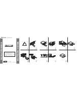
Check 4: Is the audio circuit operating normally?
Reproduce DVD-REF-A1 Title 2 Chapter (48V/16-bit/1 kHz/0dB). Verify the circuit described in Figure 2.
This check is the same for all DVD-V compatible modules.
Checks are to be conducted using GNDAU1 (sensing pins) as a reference.
If the locations, listed under "verification location 2", can be verified, there is no need to conduct verifications for the
locations listed under "verification location 1."
If the result is not satisfactory, check to see if there are any problems with the resin flux cored solder, parts and
components, in the vicinity of the main components (the section marked
4
in the circuit diagram circuit diagram).
NO.
Verification Verification
Rated
Rated
Reference
location 1
location 2
value 1
value 2
waveform
1
AOUT0
IC1601 pin-3 For
2.2V
0.8V
Waveform 3
CXK6113, include also
and over
and lower
CN1701 pin-37
2
SRCKAV
IC1601 pin-2 For
2.2V
0.8V
Waveform 3
CXK6113, include also
and over
and lower
CN1701 pin-38
4
LRCKAV
IC1701 pin-4
2.2V
0.8V
Waveform 3
CXK6113, include also
and over
and lower
CN1701 pin-36
Rated value1
Rated value 2
GND
Figure 7: Three serial output rated values
Checks are conducted with the measurement circuit below.
NO.
Verification Verification
Rated
value
Reference
location 1
location 2
waveform
4
LO
CN1701 15pin
1120
±
150mV
Waveform 4
5
RO
CN1702 12pin
1120
±
150mV
Waveform 4
Figure 8: Analog audio outputs (LO and RO) rated values
Figure 9: LO and RO output measurement circuit
NO.
Verification
Verification
Rated value 1
Rated value 2
Reference
location 1
location 2
waveform
6
IEC958
CN1702 2pin
2.2V and over
0.8V and lower
Waveform 5
Rated value
22k
AAGND
HOST I/F
RO
LO
Q1602.3
Peripheral
muting
circuit
These resistors are inserted.
Summary of Contents for AVX-P7300DVD
Page 6: ...C F 6 AVX P7300DVD 2 2 EXTERIOR 1 3 55 56 A ...
Page 8: ...8 AVX P7300DVD G D H 2 3 EXTERIOR 2 3 ...
Page 10: ...10 AVX P7300DVD B E 2 4 EXTERIOR 3 3 ...
Page 12: ...12 AVX P7300DVD 2 6 DVD MECHANISM MODULE I ...
Page 25: ...25 AVX P7300DVD 5 6 7 8 A B C D 5 6 7 8 D RELAY UNIT A CN101 D ...
Page 29: ...29 AVX P7300DVD 1 2 3 4 A B C D 1 2 3 4 3 9 PU UNIT REFERENCE ...
Page 44: ...44 AVX P7300DVD A 1 2 3 4 B C D 1 2 3 4 J D CN1101 3 12 VIDEO SCHEMATIC ...
Page 45: ...45 AVX P7300DVD 5 6 7 8 A B C D 5 6 7 8 J J VIDEO SCHEMATIC ...
Page 47: ...47 AVX P7300DVD 5 6 7 8 A B C D 5 6 7 8 E F CN1901 SIDE A A ...
Page 48: ...48 AVX P7300DVD A 1 2 3 4 B C D 1 2 3 4 AV BUS IP OUT IP IN OPT OUT SPEAKER A CONTROL PCB A ...
Page 49: ...49 AVX P7300DVD 5 6 7 8 A B C D 5 6 7 8 IC Q FRONT RGB CORD SIDE B A ...
Page 53: ...53 AVX P7300DVD 1 2 3 4 A B C D 1 2 3 4 IC Q RELAY UNIT D SIDE B D ...
Page 59: ...59 AVX P7300DVD 5 6 7 8 A B C D 5 6 7 8 ADJ M2 M3 A CN251 A CN252 C CN261 I SIDE A ...
Page 61: ...61 AVX P7300DVD 5 6 7 8 A B C D 5 6 7 8 12cmDETECT 8cmDETECT IC Q CLAMP I SIDE B ...
Page 62: ...62 AVX P7300DVD A 1 2 3 4 B C D 1 2 3 4 J D CN1101 J 4 10 VIDEO SCHEMATIC VIDEO SCHEMATIC ...
Page 63: ...63 AVX P7300DVD 5 6 7 8 A B C D 5 6 7 8 J ...
Page 89: ...89 AVX P7300DVD POWER SUPPLY 3 3V 2 7V POWER SUPPLY 3 3V Schematic diagram 2 ...
Page 93: ...93 AVX P7300DVD AUDIO 2ch ANALOG OUT POWER SUPPLY 3 3V Schematic diagram 4 ...
Page 95: ...95 AVX P7300DVD AV CHIP BLOCK POWER SUPPLY 3 3V Schematic diagram 5 ...
Page 97: ...97 AVX P7300DVD POWER SUPPLY 3 3V Schematic diagram 6 ...
Page 99: ...99 AVX P7300DVD POWER SUPPLY 3 3V CLOCK FREQUENCY 5MHz POWER SUPPLY 3 3V Schematic diagram 7 ...