background image

Function description

Operating Manual PSS u2 ES 4DO R 8A
1004548-EN-03

| 11

4.4

Outputs

Outputs

}

The head module sets the output status via the module bus.

If the module does not receive a process image of outputs from the head module, then sub-
stitute values are used for the process data. The value that is to be used as the substitute
value can be configured.

Substitute values may be:

}

Output switched off (default value)

}

Output switched on

}

Last valid value

4.5

Reaction times

Detailed information on the reaction times is available in the operating manual of the head
modules.

4.6

Energy-saving functions

The energy-saving levels are controlled by the head module and are not configurable. The
module supports the following energy-saving levels:

}

Switching off the LEDs

The LEDs have two energy-saving levels:

– Switching off the LEDs that display the terminal status

– Switching off the LEDs that display the module and terminal status

}

Switching off the relay coils

}

Standby mode

– All module functions are inactive.

– The LEDs for displaying the module and terminal status are switched off.

Summary of Contents for PSS u2 ES 4DO R 8A

Page 1: ...PSS u2 ES 4DO R 8A Operating Manual 1004548 EN 03 Control system PSS u2 Remote I O system PSS u2...

Page 2: ...ation and on an equal basis All rights to this documentation are reserved by Pilz GmbH Co KG Copies may be made for the user s internal purposes Suggestions and comments for improving this documenta t...

Page 3: ...10 4 4 Outputs 11 4 5 Reaction times 11 4 6 Energy saving functions 11 5 Address assignment 12 6 Installation 13 6 1 General installation guidelines 13 6 1 1 Dimensions 13 6 2 Protective coding on ter...

Page 4: ...Contents Operating Manual PSS u2 ES 4DO R 8A 1004548 EN 03 4 10 2 Accessories 26...

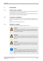
Page 5: ...al 1 3 Definition of symbols Information that is particularly important is identified as follows DANGER This warning must be heeded It warns of a hazardous situation that poses an immediate threat of...

Page 6: ...Introduction Operating Manual PSS u2 ES 4DO R 8A 1004548 EN 03 6 INFORMATION This gives advice on applications and provides information on special fea tures...

Page 7: ...s the carrier unit for the electronic modules The terminal block is plugged into the electronic modules and is used to connect the field wiring Details of the terminal blocks that can be used are avai...

Page 8: ...2 0 0 We recommend that you always use the latest version download from www pilz com 3 3 Safety regulations 3 3 1 Use of qualified personnel The products may only be assembled installed programmed com...

Page 9: ...ch it is intended Damage can be attributed to not having followed the guidelines in the manual Operating personnel are not suitably qualified Any type of modification has been made e g exchanging comp...

Page 10: ...d protection mechanisms The module has the following protection mechanisms Protective separation between both relay contacts see Technical details 23 Protective separation between both relay contacts...

Page 11: ...ast valid value 4 5 Reaction times Detailed information on the reaction times is available in the operating manual of the head modules 4 6 Energy saving functions The energy saving levels are controll...

Page 12: ...es 1 Byte in the process image of outputs PIO Meaning State Bit 0 Output data O0 N O contact O0 13 O0 14 0 N O contact is open 1 N O contact closed Bit 1 Output data O1 N O contact O1 23 O1 24 Bit 2 O...

Page 13: ...ctrostatic discharge Electrostatic discharge can damage components Ensure against discharge before touching the product e g by touching an earthed conductive sur face or by wearing an earthed armband...

Page 14: ...d to a module s switch contacts then pro tective coding must be used Protective coding prevents the terminal block from being plugged into another module 1 Insert the protective coding into the 8 pin...

Page 15: ...lugged if the terminal block has been re moved first The mechanics of the electronic modules are designed for 20 plug in out cycles On electronic modules with outputs the terminal block may only be in...

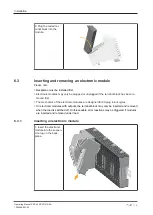
Page 16: ...4DO R 8A 1004548 EN 03 16 2 Swivel the electronic module downwards until you hear it click into place 3 Insert the terminal block into the suspen sion lug on the module 4 Swivel the terminal block upw...

Page 17: ...17 6 3 2 Removing an electronic module 1 Press the unlocking mechanism on the ter minal block that is shown by the arrow and pull off the terminal block forward 2 Press the unlocking mechanism that is...

Page 18: ...electronic module Effects Module bus communication between the other modules is not interrupted To detect the new module the following steps can be necessary Creating a new configuration or changing...

Page 19: ...evention regulations apply These voltages must only be applied at the upper terminals Ox3 to guarantee pro tection against contact when removing the terminal blocks Use copper wiring 7 1 1 Connection...

Page 20: ...onfiguration Terminal configuration Connection examples Output O0 Terminal 1 3 Contacts O0 13 O0 14 Output O1 Terminal 5 7 Contacts O1 23 O1 24 Output O2 Terminal 9 11 Contacts O2 33 O2 34 Output O3 T...

Page 21: ...al status display The module can detect the following errors 1 Colour 1 2 Colour 2 Meaning Further information Module not ready for operation Green Module ready for operation Green Green Module in ope...

Page 22: ...erature exceeds a threshold value then a warning is sent to the head module If the temperature drops back below the threshold value the module sends an all clear Too hot If the module temperature exce...

Page 23: ...Max processing time for relay output tProcOM when signal changes from 1 to 0 50 ms Max processing time for relay output tProcOM when signal changes from 0 to 1 50 ms Contact material AgSnO2 Environmen...

Page 24: ...t and relay output Type of potential isolation Protective separation Rated surge voltage 6000 V Potential isolation between Relay output and periphery supply Type of potential isolation Protective sep...

Page 25: ...fe graphs The service life graphs indicate the number of cycles from which failures due to wear must be expected The wear is mainly caused by the electrical load the mechanical load is negli gible Fig...

Page 26: ...C E1 10 pcs Labelling bracket for electronic module 23 5 x 10 5 mm scope of delivery 10 pieces 328910 PSS u2 A LC E2 10 pcs Labelling bracket for electronic module 103 x 10 5 mm scope of delivery 10 p...

Page 27: ...ckplanes Product type Features Order no PSS u2 B 1 Backplane 1 slot 328811 PSS u2 B 4 Backplane 4 slots 328810 Protective coding for terminal block Product type Features Order no PSS u2 A CE T 10 pc P...

Page 28: ...XXX en 0X 2021 01 Printed in Germany Pilz GmbH Co KG 2021 Support Technical support is available from Pilz round the clock Pilz develops environmentally friendly products using ecological materials an...

Reviews: