background image

PNOZ c2

Operating Manual PNOZ c2
22212­EN­02

7

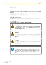
Installation

}

The unit should be installed in a control cabinet with a protection type of at least IP54.

}

Use the notch on the rear of the unit to attach it to a DIN rail.

}

Ensure the unit is mounted securely on a vertical DIN rail (35 mm) by using a fixing ele­
ment (e.g. retaining bracket or an end angle).

Wiring

Please note:

}

Information given in the "Technical details" must be followed.

}

Outputs 13­14 and 23­24 are safety contacts, the semiconductor output Y32 is an auxil­
iary output (e.g. for display).

}

Semiconductor output Y32 should 

not

 be used for safety circuits!

}

To prevent contact welding, a fuse should be connected before the output contacts (see
Technical details).

}

Use copper wire that can withstand 60/75 °C.

}

Do 

not

 connect capacitive load.

}

The power supply must comply with the regulations for extra low voltages with protect­
ive electrical separation (SELV, PELV) in accordance with VDE 0100, Part 410.

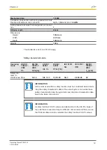
INFORMATION

The voltage at the inputs S12, S22 has to be at least 24 V DC less the lower
tolerance value of the supply voltage (s. technical details). When the voltage
is too low, increase the supply voltage until at least the lower tolerance
value is reached at the inputs.

Preparing for operation

Supply voltage

AC

DC

A1

L+

A2

L-

Input circuit

Single­channel

Dual­channel

Light guard or safe sensor with
detection of shorts across con­
tacts and short circuit proof
OSSDs

A1

A1

A1

A2

A2

A2

S12

S22

24 V DC

GND

*

*

Summary of Contents for PNOZ c2

Page 1: ...PNOZ c2 Operating Manual 22212 EN 02 Safety relays...

Page 2: ...KG Copies may be made for internal purposes Suggestions and comments for improving this documentation will be gratefully received Pilz PIT PMI PNOZ Primo PSEN PSS PVIS SafetyBUS p SafetyEYE SafetyNET...

Page 3: ...r your safety 5 Unit features 5 Safety features 6 Block diagram terminal configuration 6 Function description 6 Installation 7 Wiring 7 Preparing for operation 7 Operation 9 Status indicators 9 Faults...

Page 4: ...This warning must be heeded It warns of a hazardous situation that poses an immediate threat of serious injury and death and indicates preventive measures that can be taken WARNING This warning must b...

Page 5: ...with the documented technical details For your safety Only install and commission the unit if you have read and understood these operating instructions and are familiar with the applicable regulation...

Page 6: ...The unit is ready for operation when the start circuit is closed or when a start contact is opened and closed again in the start circuit High signal at input circuit e g light guard nor interrupted Th...

Page 7: ...welding a fuse should be connected before the output contacts see Technical details Use copper wire that can withstand 60 75 C Do not connect capacitive load The power supply must comply with the reg...

Page 8: ...ht guard Use the free connections A1 and A2 for connecting the supply voltage of the sender Start circuit feedback loop Start circuit Feedback loop automatic start monitored start NOTICE The unit auto...

Page 9: ...ircuit has opened Technical details General 710002 Approvals CCC CE EAC Eurasian T V cULus Listed Electrical data 710002 Supply voltage Voltage 24 V Kind DC Voltage tolerance 20 20 Output of external...

Page 10: ...contacts DC 1 at 24 V Max current 4 0 A Min current 0 01 A Max power 100 W Utilisation category In accordance with the standard EN 60947 5 1 Safety contacts AC15 at 230 V Max current 1 5 A Safety con...

Page 11: ...0 ms Simultaneity channel 1 and 2 Environmental data 710002 Climatic suitability EN 60068 2 78 Ambient temperature Temperature range 10 55 C Storage temperature Temperature range 40 85 C EMC EN 60947...

Page 12: ...62061 SIL CL EN IEC 62061 PFHD 1 h IEC 61511 SIL IEC 61511 PFD EN ISO 13849 1 2008 TM year Safety con tacts in stantaneous PL e Cat 4 SIL CL 3 2 31E 09 SIL 3 2 03E 06 20 INFORMATION All the units use...

Page 13: ...on the relay output If the service life graphs are not accessible the stated PFH value can be used irrespective of the switching frequency and the load as the PFH value already considers the relay s B...

Page 14: ...must be provided on all output contacts With DC contactors use flywheel diodes for spark suppression Order reference Type Features Terminals Order no PNOZ c2 24 VDC With spring loaded terminals 710 0...

Page 15: ...raNET p Pilz PIT PMCprotego PMI PNOZ Primo PSEN PSS PVIS SafetyBUS p SafetyEYE SafetyNET p the spirit of safety are registered and protected trademarks of Pilz GmbH Co KG in some countries We would po...

Reviews: