Pilz PMCtendo DD5 Operating Manual Download Page 25

EtherCAT

Operating Manual EtherCAT for, PMCtendo DD5 and PMCprotego D
1002906-EN-02

25

Bit

Value (bin)

Value (hex)

Description

00000011 00000000

03xx

Acknowledge value external

latch 2 (positive rise)

00000100 00000000

04xx

Acknowledge value external

latch 2 (negative rise)

00000101 00000000

05xx

A

cknowledge value internal

latch C (positive rise)

12 - 15

00010000 00000000

1xxx

State Digital Input 4

00100000 00000000

2xxx

State Digital Input 3

01000000 00000000

4xxx

State Digital Input 2

10000000 00000000

8xxx

State Digital Input 1

4.10

Mailbox Handling

With EtherCAT the acyclical data traffic (object channel or SDO channel) is called mailbox.
The approach of the Master is considered:

Mailbox Output

Data are sent from the Master (EtherCAT control) to the Slave

(servo amplifier). It is a requirement (read/write) of the master.

The Mailbox Output runs via the Sync Manager 0.

Mailbox Input

Data are sent from the Slave (Servo amplifier) to the Master

(EtherCAT control). The Master reads the answer from the

slave. The Mailbox Input runs via Sync Manager 1.

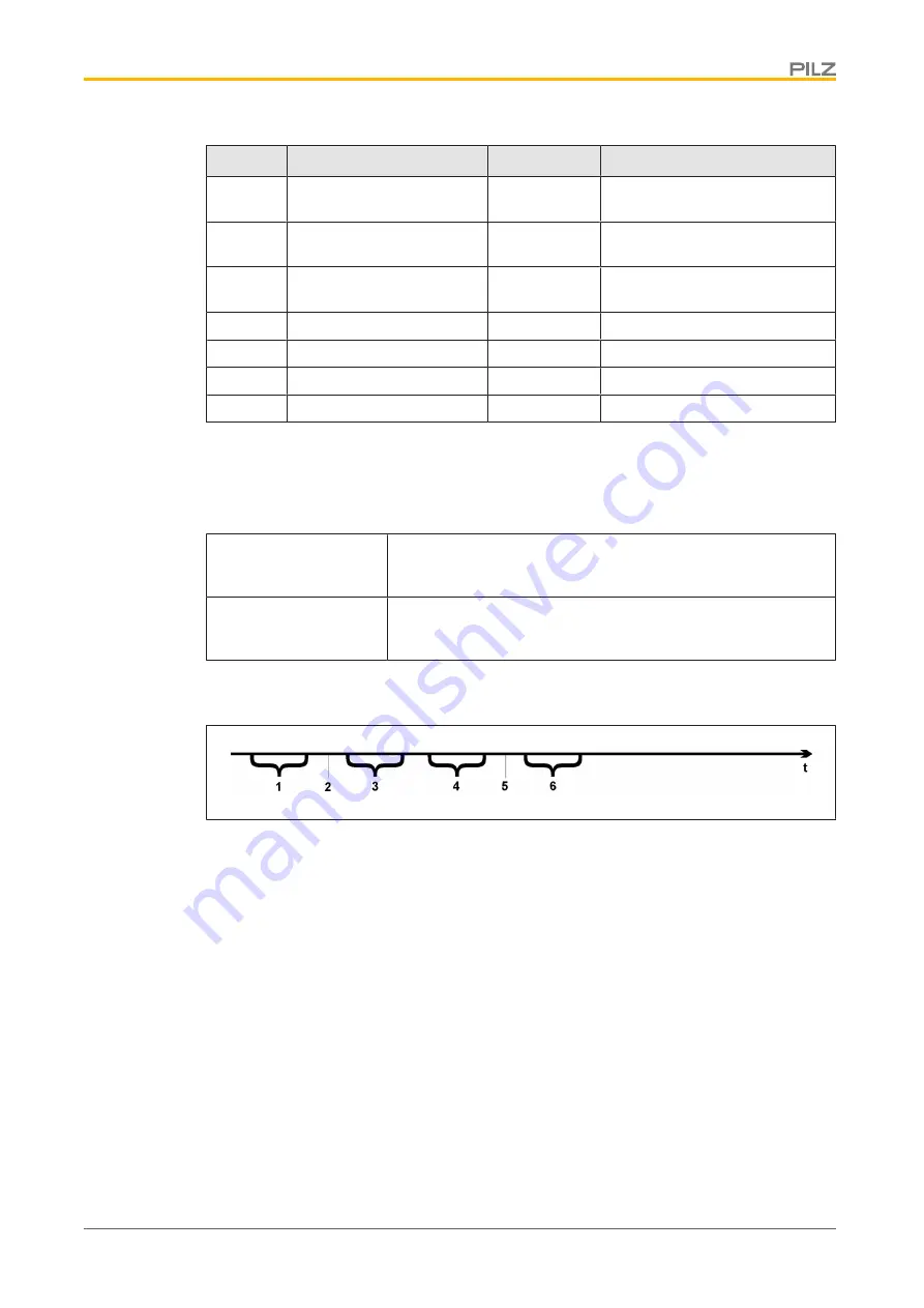
The Timing diagram illustrated the processing of a mailbox access:

Legend

1

EtherCAT Master writes the mailbox request in the Mail Out Buffer.

2

At the next interrupt, the EtherCAT interface triggers a Sync Manager 0 Event (Mail-

box Output Event) in the AL Event Register.

3

The servo amplifier reads 16 Byte from the Mail Out Buffer and copies it into an in-

ternal Mailbox Output Array.

4

The servo amplifier detects new files in the internal mailbox output array, and it ex-

ecutes the SDO access to the object requested by the EtherCAT interface. The reply

from the servo amplifier is written to an internal Mailbox Input Array.

5

The servo amplifier deleted all the data in the internal Mailbox Output Array and

paves the way for a new mailbox access.

6

The servo amplifier copies the response telegram from the internal Mailbox Input Ar-

ray into the mail in the buffer of the EtherCAT interface.

Summary of Contents for PMCtendo DD5

Page 1: ...EtherCAT for PMCtendo DD5 and PMCprotego D Operating Manual 1002906 EN 02 Servo amplifiers...

Page 2: ...nta tion will be gratefully received Source code from third party manufacturers or open source software has been used for some components The relevant licence information is available on the Internet...

Page 3: ...4 4 2 1 Interrupt enable register address 0x0204 0205 14 4 2 2 AL Event address 0x220 0221 14 4 3 Phase runup 15 4 3 1 AL Control address 0x0120 0x0121 15 4 3 2 AL Status address 0x0130 0x0131 16 4 3...

Page 4: ...dard version for the Eth erCAT protocols This manual is a component of the overall documentation of the digital servo amplifiers Installation and commissioning of the servo amplifiers and all the stan...

Page 5: ...of a hazardous situation that could lead to serious injury and death and indicates preventive measures that can be taken CAUTION This refers to a hazard that can lead to a less serious or minor injury...

Page 6: ...site FTP File Transfer Protocol HW Hardware ICMP Internet Control Message Protocol Protocol to display IP errors IEC International Electrotechnical Commission International standardisation committee...

Page 7: ...se Locked Loop PTP Precision Time Protocol in accordance with IEEE 1588 RSTP Rapid Spanning Tree Protocol RT Real time possible in Ethernet Controller without additional support RT Frames EtherCAT tra...

Page 8: ...1 Intended use Please note the chapters Intended use and Improper use in the operating manual of the servo amplifier The sole purpose of the EtherCAT interface is to connect the servo amplifier to a M...

Page 9: ...le of contents and index are active bookmarks Table of contents and index in the text The lines are active cross references Click the required line to display the corresponding page Page number in the...

Page 10: ...rotating WARNING Possible loss of the safety Electronic devices are not fail safe as a matter of principle The user is re sponsible that the drive is led to a safe condition for machinery or personnel...

Page 11: ...remental value positioning accuracy etc refers to the arithmetic values Non linearities in the mechanics back lash elasticity etc are not considered If the motor s end speed needs to be changed all th...

Page 12: ...r Commissioning the basic functions Commission the basic functions of the servo amplifier and optimise the current speed and position controller This part of the com missioning process is described in...

Page 13: ...e r r w 0x0204 2 Interrupt enable register r r w 0x0220 2 AL Event IRQ Event r w r 0x0800 8 AL Manager 0 Mail Out control register r w r 0x0808 8 AL Manager 1 Mail Out control register r w r 0x0810 8...

Page 14: ...plete communication 0x204 3 7 r w r Reserved Mail Out Event 0x205 0 r w r Activating the Mailbox Output Event SDO Sync Manager 0 for the object channel Mail In Event 0x205 1 r w r Activating the Mailb...

Page 15: ...Reserved 4 3 Phase runup The registers AL Control AL Status and AL Status Code are responsible for the communic ation phase runup also called EtherCAT change of state and the display of the current st...

Page 16: ...e e g with not permitted transition Reserved 0x130 7 5 w r Appl specific 0x130 15 8 w r 4 3 3 AL Status Code address 0x0134 0x0135 Parameter Address Bit ZA Drive ZA ECAT Description Status 0x134 7 0 w...

Page 17: ...does not yet created cyclical interrupts the warning n17 no sync ap pears in the amplifier PI 0x01 Deactivation of all EtherCAT Events except AL control and stop ping of mailbox activities PS 0x04 Th...

Page 18: ...nables the editing of the control word and therefore the acceptance and processing of the cyclical PDO set values OS 0x04 Locking the set value acceptance OP 0x02 The ECAT interface no longer produces...

Page 19: ...ecause there is no power switched on Ready to Switch On In the Ready to Switch On status the servo amplifier must be brought to the enable state using the control word Switched On In Switched On statu...

Page 20: ...lue enable Bit 2 Enable for Bit 3 and display Bit 5 in the status word Bit 1 Cancel switch on disable Bit 0 Switch on enable when Bit 1 1 0 X X X X X 1 X X X 0 X 2 X X X 1 0 3 X X 1 1 P 4 X P 1 1 1 5...

Page 21: ...mode referen cing OPMODE 8 12 Transmit a SAVE command Action with negative edges in the control word Bits Bit 0 Switch off drive transmit the ASCII command DS 1 If Bit 1 has no negative edge brake an...

Page 22: ...Target reached in position Bit 11 1 Restrictions active e g hardware or software end switch has triggered Bit 12 1 Reference run active Bit 13 1 Reference run error Bit 15 1 Motion task active in prof...

Page 23: ...ion of the drives should be deactivated if possible ANOUT1 0 ANOUT2 0 ANCNFG 1 Interface Cycle time PMCprotego D Position 0 25 ms 250 s Speed 0 25 ms 250 s Torque 0 25 ms 250 s 4 8 Synchronisation bas...

Page 24: ...00000010 00000000 02xx Read external latch 1 negative rise 00000011 00000000 03xx Read external latch 2 positive rise 00000100 00000000 04xx Read external latch 2 negative rise 00000101 00000000 05xx...

Page 25: ...ilbox Input Data are sent from the Slave Servo amplifier to the Master EtherCAT control The Master reads the answer from the slave The Mailbox Input runs via Sync Manager 1 The Timing diagram illustra...

Page 26: ...13 14 15 CAN over EtherCAT specific data CoE Header CAN specific data standard CAN SDO Byte 0 Length of the following data from Byte 2 Low Byte Byte 1 Length of the following data from Byte 2 High By...

Page 27: ...responds to each telegram with a response in the Mailbox Input Buffer 4 10 2 Mail Input Te serve amplifier responds to each CoE telegram with a 16 Byte response telegram in the Mailbox Input Buffer T...

Page 28: ...te 9 Low Byte of the CAN object number index Byte 10 High Byte of the CAN object number index Byte 11 Subindex in accordance with the CANopen specification for the Pilz servo ampli fier Byte 12 Data L...

Page 29: ...001704 The response from the servo amplifier must be Byte 0 0x0E The following 14 Bytes include data from Byte 2 to Byte 15 Byte 1 0x00 The following 14 Bytes include data from Byte 2 to Byte 15 Byte...

Page 30: ...etyNET p THE SPIRIT OF SAFETY are registered and protected trademarks of Pilz GmbH Co KG in some countries We would point out that product features may vary from the details stated in this document de...

Reviews: