


PSEN ma1.3b-28 VA
Operating Manual PSEN ma1.3b-28 VA
22226-EN-03
| 15
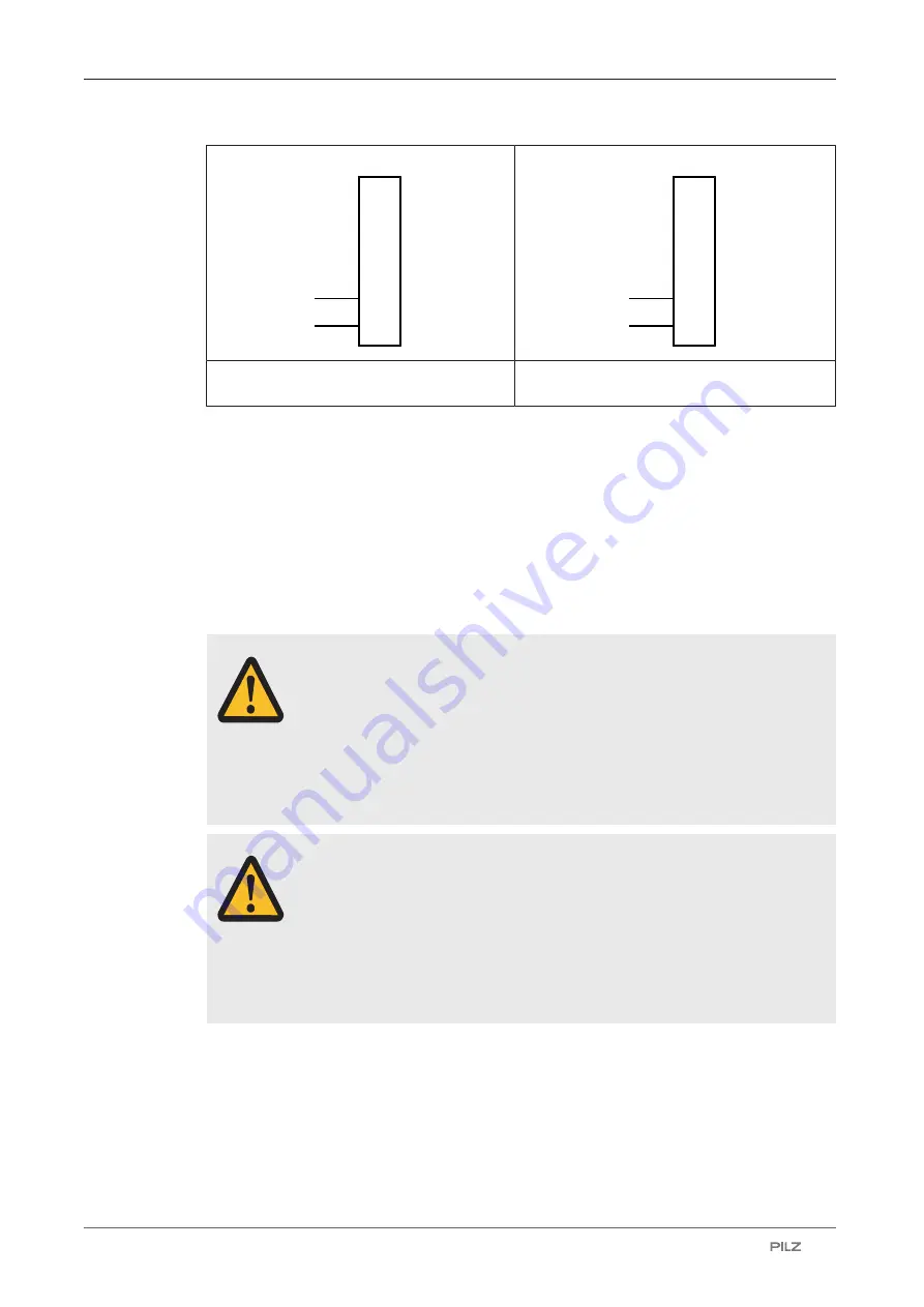
1
2
3
4
5+
6
24 V
GND
PSENmag
1
2
3
4
5+
6
24 V
PLC
PSENmag
Connecting the auxiliary contact to an eval-
uation device
Connecting the auxiliary contact to a PLC
Installation
}
The unit can be installed in any position. Safety switches and actuators must be installed
so that the sensing face of the safety switch is exactly opposite the sensing face of the
actuator.
}
If possible, do not install the safety switch and actuator on to ferromagnetic material.
Changes to the operating distances are to be expected.
}
Make sure that the earthing is in accordance with the specifications in EN 60079-14.
CAUTION!
Potential loss of safety function due to changed device properties
The unit's properties may be affected if installed in an environment contain-
ing electrically or magnetically conductive material.
– Please check the operating distances and the assured release dis-
tance.
CAUTION!
Possible loss of the safety function by changing the release distance
S
ar
with non-flush installation
Installing the safety switch non-flush within electrically or magnetically con-
ductive material, the value for the assured release distance
S
ar
can change.
– Check the assured release distance
S
ar.
}
Safety switches and actuators must be positioned so that they are secured against a
change of position.
}
The safety switch and actuator should only be secured using screws and nuts made of
non-magnetic material (e.g. brass or stainless steel).
}
Avoid the risk of damages from foreseeable external influences by attaching the safety
switch and actuator. If necessary, safety switch and actuator have to be protected.