


Supplementary data
Operating Manual PSSu K F EI
1003303-EN-03
| 62
}
Safe Stop 2 Monitoring (SS2-M)
The safety functions of the PSSu K F EI are monitoring functions, whereby a safe output
signal is used to show if defined limit values are exceeded.
The reaction function that takes place (e.g. shutting down the drive, activating a mechanical
brake) when exceeded limit values are detected during the normal operation of the safety
function must be defined and implemented by the machine/plant developer and does not
form part of the PSSu K F EI.
The monitoring function of the PSSu K F EI can be used to implement safety functions
defined in the standard EN 61800-5-2 for Adjustable speed electrical power drive systems.
Safety functions in accordance
with
EN 61800-5-2
Implemented with monitoring function of the
PSSu K F EI
Safe Operating Stop
(SOS)
Safe Operating Stop Monitoring (SOS-M)
Safe Speed Range (SSR)
Safe Speed Range Monitoring (SSR-M)
Safe Direction
(SDI)
Safe Direction Monitoring (SDI-M)
Safe Speed Monitoring
(SSM)
Safe Speed Monitoring (SSM)
Safe Stop 1
(SS1)
Safe Stop 1 Monitoring (SS1-M)
Safe Stop 2
(SS2)
Safe Stop 2 Monitoring (SS2-M)
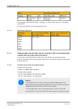
9.1.3
Safety-related characteristic data for operation with non-safety-related
encoder without additional requirements
9.1.3.1
Permitted sensor types and output signals
Permitted encoder types:
}
Rotary non-safety-related encoders
}
Linear non-safety-related encoders
Permitted output signals:
}
Square output signals TTL, single ended
}
Square output signals TTL, differential
}
Square output signals HTL, single ended
}
Square output signals HTL, differential
}
Sin/Cos output signals 1Vss, reference voltage
}
Sin/Cos output signals 1Vss, differential
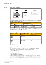
9.1.3.2
Safety-related architecture
To calculate the safety function you will need the following data for the "sensor" subsystem
and the subsystem PSSu K F EI:


