


Function description
Operating Manual PSSu K F EI
1003303-EN-03
| 34
CAUTION!
Appropriate installation measures should be taken to prevent a foreign body
coming between the signal encoder and the proximity switch. If not, the for-
eign body could cause invalid signals.
}
Please note the values stated in the sensor's technical details.
}
For a full configuration, the maximum frequency of the sensors you are using must be
entered in PAS4000 (see sensor's data sheet).
4.10
Encoder
}
The following encoders can be used:
– TTL, HTL (single-ended or differential signals)
– Sin/Cos 1 Vss
– Hiperface®
}
The encoders can be connected with or without Z index (0 index).
}
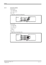
The cables used to connect the encoders must be shielded (see connection diagrams in
the chapter entitled "EMC-compliant wiring").
}
A pnp proximity switch can also be connected to track Z for monitoring broken shearpins.
Please note:
Monitoring for broken shearpins does not become active until
– The minimum speed has been exceeded and
– The tolerance for detecting feasibility errors has elapsed.
The minimum speed and tolerance depend on the ratio of the frequency at tracks AB "
f
AB
"
to the frequency at track Z "
f
Z
" in your configuration.
Minimum speed:
– Calculated ratio AB/Z
≥ 1.0
f
Z
= 10 mHz or
f
AB
= (
f
AB
/f
Z
)
x
10 mHz
– when
f
AB
/f
Z
Verh.
< 1.0
f
AB
= 10 mHz or
f
Z
= 10 mHz/(
f
AB
/
f
z
)
Tolerance for detecting feasibility errors:
– when
fAB/fZ Verh.
≥ 1.0
7.5 Z-pulses or 7.5
x
(f
AB
/f
Z
) AB-pulses
– when
fAB/fZ Verh.
< 1.0
4.5
AB-pulses or
4.5/(f
AB
/f
Z
)
Z-pulses
}
With Hiperface encoders, only the RefSin and RefCos tracks are recorded and monitored
(see
}
Track S can be used:
– To connect an encoder's error output.
– To monitor voltages between 0 V and 30 V for a permitted upper and lower limit. For
example, the encoder's supply voltage can be monitored.


