PX200 V2 Manual
1
Rev 1.1, Released, 15-01-2018
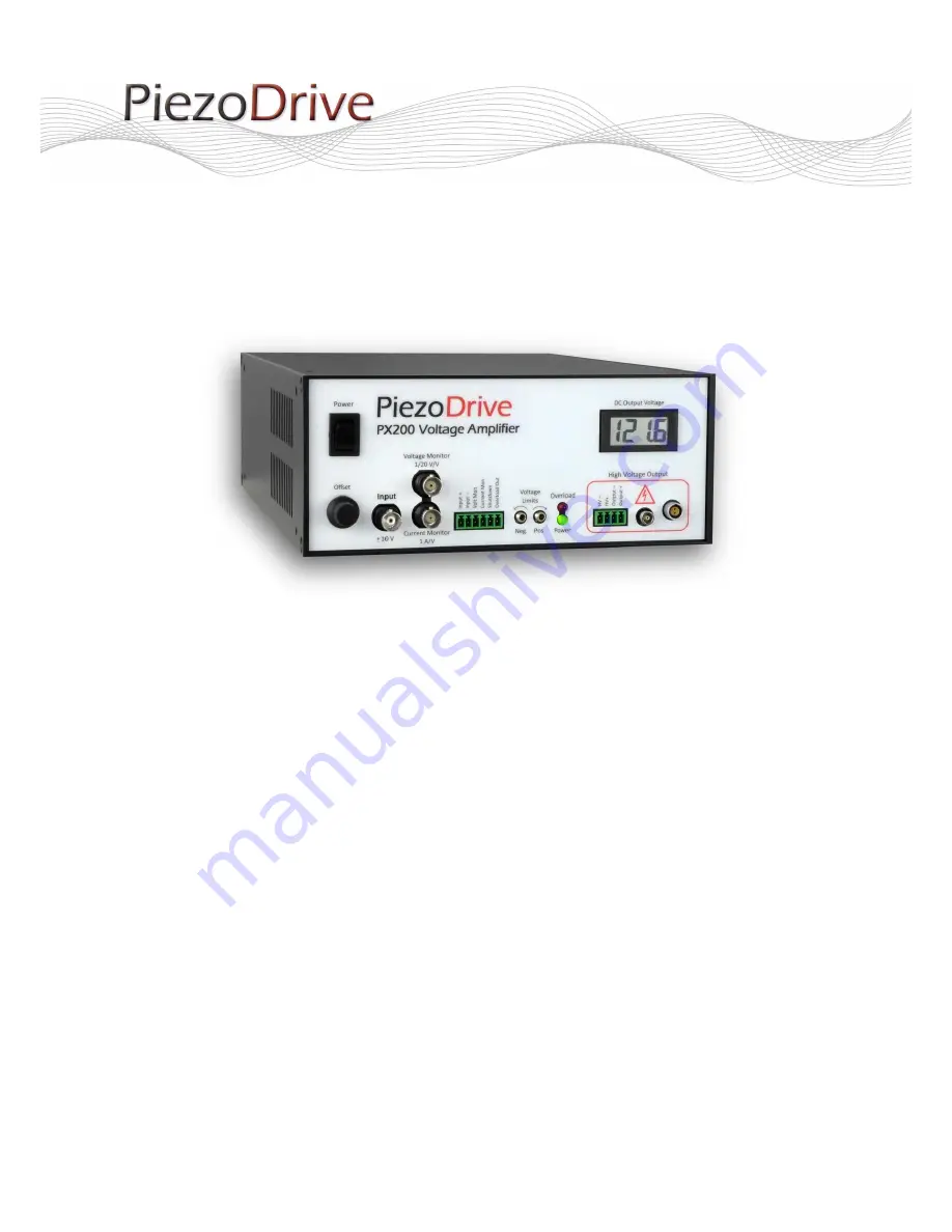
PX200 – Power Amplifier
Version 2.0
Manual and Specifications
Page 1: ...PX200 V2 Manual 1 Rev 1 1 Released 15 01 2018 PX200 Power Amplifier Version 2 0 Manual and Specifications ...
Page 2: ...Voltage Range 5 5 Output Current 5 6 Pulse Current Option 6 7 Power Bandwidth 7 8 Small Signal Bandwidth 9 9 Noise 10 10 Front Panel 11 11 Amplifier Configuration 12 12 Bridged Mode 13 13 Overload and Shutdown 14 14 Front Panel Connectors 15 14 1 HV Output 16 14 2 LEMO OB Cable Assembly 17 15 Enclosure 18 16 Warranty 18 ...
Page 3: ...8 Amps peak for pulse applications The PX200 is compact lightweight and can be powered from any mains supply The output connectors include LEMO 00 LEMO 0B BNC adaptor included and plug in screw terminals so many commercially available piezoelectric actuators can be directly connected The PX200 is suited to a wide range of applications including electro optics ultrasonics vibration control nanoposi...
Page 4: ...al Bandwidth 390 kHz Max Power 140 W Dissipation Load Any Noise 150 uV RMS 10uF Load 0 03 Hz to 1 MHz Protection Continuous short circuit thermal Voltage Monitor 1 20 V V BNC Current Monitor 1 V A BNC Analog Input Signal input BNC Zin 48 7k Output Connectors LEMO 0B LEMO 00 Screw Terminals BNC Power Supply 90 Vac to 250 Vac Mechanical Specifications Environment 0 40 C 32 104 F Non condensing humid...
Page 5: ...V100 50 100 to 100 1 5 A 2 A PX200 V100 100 100 to 0 3 1 A 4 A PX200 V100 0 150 to 0 2 0 A 4 A PX200 V150 0 200V to 0 1 5 A 2 A PX200 V200 0 Table 1 Voltage range configurations 5 Output Current The PX200 has a peak and average current limits as described in Table 1 The RMS current limit defines the maximum frequency that is achievable with a capacitive load This topic is discussed in Power Bandwi...
Page 6: ... 8 Amps and the maximum pulse duration is reduced to the time listed in Table 2 The voltage span is the peak to peak output voltage range e g the voltage span for the 50V to 150V range is 200V Voltage Span Pulse Current Pulse Time 200 V 8 A 150 us 150 V 8 A 200 us 100 V 8 A 300 us 50 V 8 A 300 us Table 2 Maximum peak current duration in the pulse configuration For a current pulse that is less than...
Page 7: ...t full output voltage When the amplifier output is open circuit the power bandwidth is limited by the slew rate however with a capacitive load the maximum frequency is limited by the RMS current and load capacitance The power bandwidth for a range of capacitive loads is listed below Load Capacitance 50V Range 100V Range 150V Range 200V Range 10 nF 222 kHz 111 kHz 74 kHz 55 kHz 30 nF 222 kHz 111 kH...
Page 8: ...PX200 V2 Manual 8 Rev 1 1 Released 15 01 2018 200V Range 150V Range 100V and 50V Range Ra Figure 2 Maximum peak to peak voltage versus frequency and load capacitance ...
Page 9: ... a range of load capacitances Load Capacitance Bandwidth 10 nF 393 kHz 30 nF 431 kHz 100 nF 367 kHz 300 nF 208 kHz 1 uF 88 kHz 3 uF 30 kHz 10 uF 9 3 kHz 30 uF 3 7 kHz 110 uF 1 3 kHz Table 4 Small signal bandwidth versus load capacitance 3dB 10 3 10 4 10 5 10 6 20 10 0 10 20 30 Magnitude dB 10 3 10 4 10 5 10 6 250 200 150 100 50 0 50 100 Phase deg Frequency Hz 300 nF 1 uF 3 uF 10 uF 30 uF 100 nF 30...
Page 10: ...03 Hz to 20 Hz The high frequency noise 20 Hz to 1 MHz is listed in the table below versus load capacitance The total RMS noise from 0 03 Hz to 1 MHz is found by summing the RMS values that is 𝜎 𝜎𝐿𝐹 2 𝜎𝐻𝐹 2 For a load capacitance of less than 1 uF the noise is primarily broadband thermal noise however for a capacitance of greater than 1 uF the noise is primarily due to low frequency noise Load Cap...
Page 11: ...utdown Input A voltage from 2V to 24V relative to Input disables the amplifier Overload Out Output 5V output when the amplifier is disabled or in overload state Voltage Limits Limits the maximum negative and positive output voltage Overload RED when the amplifier is disabled or in an overload state Power GREEN when the power is on HV Output Connected to the negative high voltage power supply rail ...
Page 12: ... Inverting INV Gain 20 default Gain 10 Gain10 Table 6 Amplifier configuration The DC offset control is configurable with a positive range or a bipolar range The front panel potentiometer can be disabled by enabling a PCB mounted trim pot Offset Configuration Order Code Notes 0V to 200V Offset Range default 200V Offset Range OR2 Front panel source default PCB trim pot source OS2 Disables front pane...
Page 13: ...h the negative terminal the current monitor is disabled however the overload and protection features are unaffected Common bridged mode configurations are listed in Table 7 Figure 5 Bridge mode configuration for obtaining 200V Load Voltage RMS Current Positive Amp Negative Amp 200V 1 5 A PX200 V100 100 PX200 V100 100 INV 100V 3 1 A PX200 V50 50 PX200 V50 50 INV 0V to 200V 3 1 A PX200 V0 100 PX200 ...
Page 14: ...ut signal is 5V During an overload or shutdown state the output is partially disabled and may float at approximately 50 of the voltage range When the amplifier is switched on the overload protection circuit is engaged by default and clears after three seconds The amplifier can be shut down by an external source by applying a voltage of between 2V and 24V to the Shutdown input relative to Input The...
Page 15: ...erminal TJ0431530000G Amphenol OQ0632510000G 4 Way Screw Terminal TJ0631530000G Amphenol OQ0432510000G LEMO 00 FFA 00 250 LEMO EPL 00 250 LEMO 0B FGG 0B 302 LEMO EPG 0B 302 The LEMO 0B connector is recommended for applications requiring more than 1 Amp RMS output current Preassembled LEMO cable assemblies are available from www PiezoDrive com A LEMO 00 to Female BNC adaptor cable PD 00 FBNC 30 is ...
Page 16: ...and the internal HV supply rails The Output signal is connected to ground through a 0 1 Ohm resistor Stack actuators are connected as shown below Bender actuators can be driven with a single bias voltage for example 200 V or a bipolar bias voltage for example 100 V The 100 V bipolar configuration is shown below HV Output Output HV 100V 100V to 100V 100V ...
Page 17: ...lugs Dimension Solder Terminals Crimp Terminals L Free Length 13 mm 17 mm S Shield Length 7 mm 7 mm T Strip Length 3 mm 4 mm The parts list for the LEMO 0B 302 plug are FGG 0B 302 CLAZ solder terminals or FGG 0B 302 CYCZ crimp terminals FGG 0B 742 DN collet for 3 1mm to 4mm cable GMA 0B 035 DN strain relief boot for 3 5mm to 3 9mm cable The plug assembly process is 1 Strip the cable as above 2 If ...
Page 18: ...r a thermal overload state as discussed in Overload and Shutdown The PX200 can be installed in a 19 inch x 2U rack space using the PX200 Rack1 kit Two amplifiers can also be installed in a side by side configuration using the PX200 Rack2 kit 16 Warranty PiezoDrive amplifiers are guaranteed for 3 months The warranty does not cover damage due to misuse or incorrect user configuration of the amplifie...