Technical Manual
MT 188-E
8
Wdsu
= tripping range due to slam-shut valve pressure decrease,
which can be obtained by using the setting spring mounted during final
testing.
Wdu
= tripping range due to slam-shut valve pressure decrease, which
can be obtained by using the setting springs listed in the tables.
4.2
GAS FEEDING, CHECK OF EXTERNAL
TIGHTNESS AND CALIBRATIONS
Pressure feeding to the equipment shall be performed very slowly.
When not any inertization procedure is implemented, it is
recommended to keep gas speed in the feeding piping under a value of
5 m/sec during the pressure feeding phase.
In order to prevent the equipment from being damaged, the following
shall be absolutely avoided:
- Pressurization through a valve positioned downstream of the
equipment itself.
- Depressurization through a valve positioned upstream of the
equipment itself.
The external tightness is assured when by applying a foam medium on
the element under pressure no bubbles are produced.
Usually, the slam-shut valves are supplied already calibrated to the
requested value. However, it may happen that due to several reasons
(e.g. vibrations during transport) the calibrations may be subject to
slight changes, though remaining within the range of the values
allowed by the springs used. Therefore, it is advisable to verify the
calibrations according to the procedures outlined here below.
Before commissioning the valve, it is necessary to verify that all
on/off valves (inlet, outlet, and bypass - if any) are closed and that
the gas has such a temperature as not to create malfunctions.
4.3
CALIBRATION CHECK
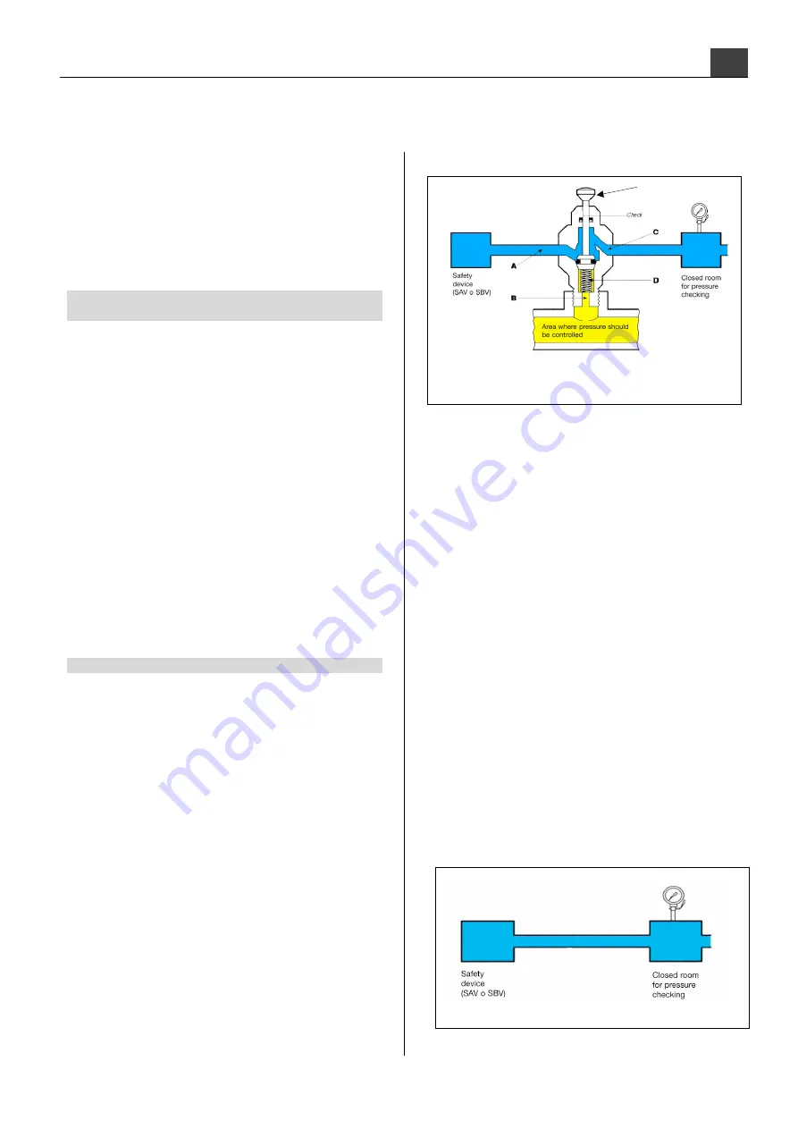
Check and record the tripping of the slam-shut device as follows:
A) For the slam-shut devices connected to the downstream piping
through the "push" three-way switch valve, proceed as follows
(Fig. 10):
Fig. 10
- connect to the way C a controlled auxiliary pressure;
- restore the slam-shut device by means of the suitable lever;
- press knob 1 and:
•
For safety devices tripping in case of maximum pressure slowly
increase the auxiliary pressure and verify the tripping value.
If necessary, increase the tripping value by rotating clockwise
the adjustment ring nut or decrease the tripping value by rotating
it counter-clockwise.
•
For safety devices tripping in case of pressure increase and
decrease, slowly increase the auxiliary pressure and record the
tripping value.
If necessary, increase the tripping value by rotating clockwise
the adjustment ring nut or decrease the tripping value by rotating
it counter-clockwise.
Decrease the auxiliary pressure and perform the device
restoration procedure.
Slowly decrease the auxiliary pressure and verify the tripping in
case of pressure decrease. If necessary, increase the tripping
value by rotating clockwise the adjustment ring nut or decrease
the tripping value by rotating it counter-clockwise.
- make sure that the operation is fine by repeating the procedure for at
least 2-3 times.
- disconnect the controlled auxiliary pressure from way C;
B) For the devices not equipped with "push" valve, it is recommended
to connect separately the control head at a controlled auxiliary
pressure and repeat the operations described above (Fig. 11).
Fig. 11
fig.


