


42
42
42
42
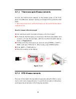
3.6 Diode Measurements
M3500A uses a current source of 1 mA for diode testing. The maximum
resolution is 10 µV on a fixed range of 1 V DC. The default threshold
voltage is fixed between 0.3 and 0.8 volts and the reading rate is fixed at
0.1 PLC (The voltage bound is adjustable from 0.01V up to 1.2V.). A
“Beep” sound will appear when the diode measured value is in the range.
Warning! Positive end of the source signal is to be connected to HI
of the input terminals, and the negative end to LO of the input terminals.
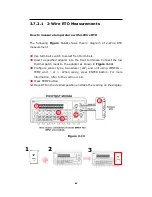
How to measure diode
①
①
①
①
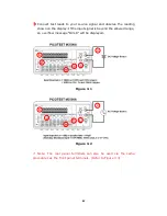
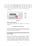
Selects input signal connections on front or rear panel.
②
②
②
②
Connect the diode to the terminals. For forward bias, connect the
probe from input terminal “
HI
” to the positive end of the diode, and
connect the probe from input terminal “LO” to the negative end of the
diode.
③
③
③
③
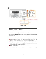
Set voltage bound via pressing CONFIG + SHIFT + CONT buttons.
When ready, press ENTER. (Or skip this step if you wish to use the
default voltage bound.)
④
④
④
④
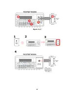
Press SHIFT + CONT buttons to select the diode testing function and
observe the reading on the display.
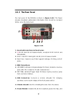
Figure 3-11
1
3
4
2
4
Summary of Contents for M3500A
Page 1: ...PICOTEST M3500A 6 5 Digit Digital Multimeter User s Manual Version 1 06 ...
Page 2: ...2 2 2 2 M3500A DMM User s Manual ...
Page 49: ...49 49 49 49 Figure 3 17 1 2 3 5 5 4 4 1 2 3 ...
Page 50: ...50 50 50 50 Figure 3 18 5 ...
Page 191: ...191 191 191 191 FreeLibrary hUSBTMCLIB hUSBTMCLIB NULL return ...