background image

4

Installation: 

The TELink should be installed using the following steps:

Step 1:

 Wall or shelf mount the unit. Screws and rubber feet are supplied in the accessory kit. 

Step 2:

 If connecting to an amplifier make sure it is turned OFF for this part of the installation.

Step 3:

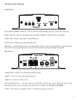
 Connect the supplied grounding wire from the SURGE GND terminal to the buildings electrical ground.

Step 4:

 Connect a RCA cable (supplied in the accessory kit) to the OUTPUT jack on the rear of the unit. Depending 

upon the required impedance use either the 8Ω or 600Ω output RCA jack. Connect the other side to the MOH port 

on the phone system, PA system or speaker. 

Step 5:

 Connect the incoming line to the LINE IN then connect the LINE OUT to a PHONE, FAX or KSU.

Step 6:

 Attach the included power pack to a wall or power strip receptacle, then attach the other end to the jack on 

the rear of the unit labeled 12VDC.

Step 7:

 If any amplifiers were turned OFF during installation then turn them back ON now.

Step 8:

 Adjust the volume level (while on hold) using up and down VOLUME buttons on the front of the unit. 

Depending upon the application either call into the phone system and be placed on hold OR listen to the PA 

systems speakers to fine tune volume. If volume controls are locked then the servicing dealer may need to assist 

with this step. 

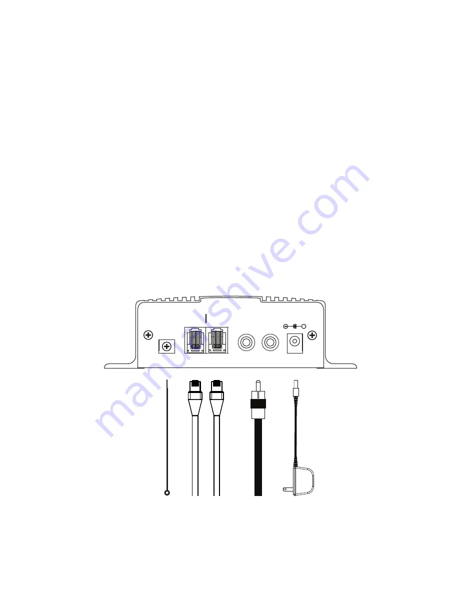
Wiring Diagram

SURGE

GND

LINE

IN

600Ω

MADE IN USA

12VDC

500mA

+

OUTPUT

LINE

OUT

Incoming  

Telco Line

Phone, Fax or KSU

To MOH or P

A

 System

(Use 8Ω or 600Ω)

Building Ground

Summary of Contents for TELink 700a

Page 1: ...TELink 700a 700an Installation User Manual...

Page 2: ...ight message for callers Unpacking and Inspection Before you begin installation unpack and verify you have all the correct parts 1 TELink 1 12VDC 500mA power supply 1 Instruction manual 1 RCA to RCA c...

Page 3: ...itch has no effect on the audio output connections on the rear of the unit Switch should normally be kept OFF Rear of Unit SURGE GND Connects to the buildings electrical ground LINE IN Connects to the...

Page 4: ...5 Connect the incoming line to the LINE IN then connect the LINE OUT to a PHONE FAX or KSU Step 6 Attach the included power pack to a wall or power strip receptacle then attach the other end to the ja...

Page 5: ...at 9am and ON at 5pm Monday Friday with no ON or OFF time scheduled for Saturday and Sunday Under this schedule Night Answer is active during non business hours 5pm 9am and all weekend long Manual No...

Page 6: ...nication mode New audio being downloaded MOH message not playing Check volume output level by adjusting the VOLUME Check OUTPUT connection from unit to phone or PA system Try switching between the 8 a...

Page 7: ...ment of any eligible part or equipment covered under this warranty through a PICA Product Development LLC dealer only Buyer is responsible for all shipping and handling charges in connection with the...

Page 8: ...PICA Product Development LLC 4 Ash Street Extension Unit 1 Derry NH 03038 picapd com Rev 1 17 Copyright 1984 2017 by PICA Product Development LLC...

Reviews: