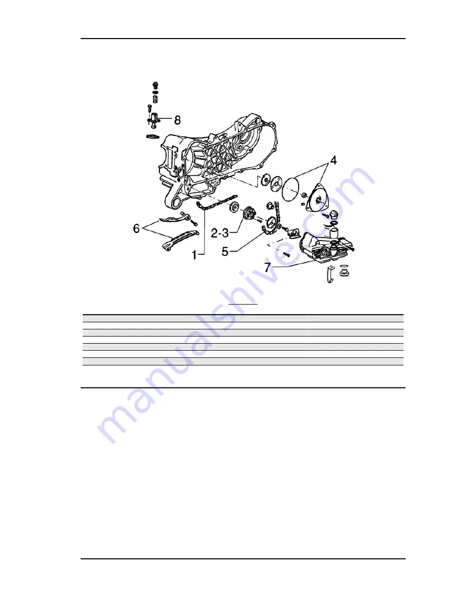
background image

Oil pump

O

IL


PUMP

Code

Action

Duration

1

001051

Belt/Timing chain - Change

2

001112

Oil pump - change

3

001042

Oil pump - Service

4

001121

Chain cover oil seal - Replacement

5

001122

Oil pump chain - Replacement

6

001125

Chain guide pads - Replacement

7

001130

Oil sump - Replacement

8

001129

Chain tightener - Overhaul and re-

placement

MSS ZIP 100 4T

Time

TIME - 161

Summary of Contents for MSS ZIP 100 4T

Page 1: ...SERVICE STATION MANUAL 633734 633741 MSS ZIP 100 4T...

Page 2: ...changes to components parts or accessories which it considers necessary to improve the product or which are required for manufacturing or construction reasons Not all versions models shown in this pu...

Page 3: ...to read the sections of this manual relating to appropriate tools along with the appropriate tool catalogue N B Provides key information to make the procedure easier to understand and carry out CAUTIO...

Page 4: ......

Page 5: ...RACTERISTICS CHAR TOOLING TOOL MAINTENANCE MAIN TROUBLESHOOTING TROUBL ELECTRICAL SYSTEM ELE SYS ENGINE FROM VEHICLE ENG VE ENGINE ENG SUSPENSIONS SUSP BRAKING SYSTEM BRAK SYS CHASSIS CHAS PRE DELIVER...

Page 6: ...INDEX OF TOPICS CHARACTERISTICS CHAR...

Page 7: ...ot breathe in the dust produced by the wear of the friction material Even though the latter contains no asbestos inhaling dust is harmful Maintenance rules Use original PIAGGIO spare parts and lubrica...

Page 8: ...n to the left side Depression carburettor KEIHIN CVK CO adjustment 3 2 0 5 Engine idle speed 100 cc 1500 150 rpm Air filter sponge impregnated with a mixture 50 oil Selenia Air Filter Oil and 50 unlea...

Page 9: ...RG 4 PHP NGK CR9EB Fuse 100 cc 10 A Generator single phase alternating current Frame and suspensions FRAME Specification Desc Quantity Type of chassis Welded tubular steel chassis with stamped sheet...

Page 10: ...eaned through the filter B gets into the reed valve C to be directed towards the head through a flexible pipe and then a rigid one D flanged to the head In this way the air reaches the discharge pipe...

Page 11: ...screw 5 6 5 N B IN ORDER TO ENSURE AN ADEQUATE LOCKING TORQUE LUBRICATE THE NUTS BEFORE ASSEMBLING THEM ENGINE ASSEMBLY Name Torque in Nm Ignition spark plug 10 15 Nm Head cover screws 8 10 Head cyli...

Page 12: ...ew 8 10 Overhaul data Assembly clearances Cylinder piston assy COUPLING BETWEEN PISTON AND CYLINDER Name Initials Cylinder Piston Play on fitting Cylinder C 50 0 021 0 007 A 49 993 50 000 49 948 49 95...

Page 13: ...614 50 562 50 569 0 038 0 052 Piston 3rd Oversize P 50 562 0 014 D3 50 614 50 621 50 569 50 576 0 038 0 052 Piston rings SEALING RINGS Name Description Dimensions Initials Quantity 1st Compression ri...

Page 14: ...AND CONNECTING ROD Name Description Dimensions Initials Quantity Half shaft transmission side 14 0 0 005 A Flywheel side half shaft 16 0 0 005 B Connecting rod 14 8 0 05 0 C Built up camshaft 45 00 Fi...

Page 15: ...stic Shimming system to control the compression ratio CR 10 5 11 5 1 CYLINDER HEIGHT 54 95 0 05 HEAD GASKET THICKNESS steel 0 3 0 05 BASE GASKET THICKNESS Specification Desc Quantity Size measured A 0...

Page 16: ...5W 40 API SL ACEA A3 JASO MA Synthetic oil AGIP BRAKE 4 Brake fluid FMVSS DOT 4 Synthetic fluid MONTBLANC MOLYBDENUM GREASE Grease for driven pulley shaft adjusting ring and movable driven pulley hou...

Page 17: ...INDEX OF TOPICS TOOLING TOOL...

Page 18: ...008 Pliers to extract 17 mm bearings 001467Y029 Bell for bearings O D 38 mm 005095Y Engine support 008119Y009 Tube to assemble shafts and axles 020004Y Punch for removing fifth wheels from headstock 0...

Page 19: ...escription 020151Y Air heater 020392Y Fork to assemble piston and cylinder 020329Y Mity Vac vacuum operated pump 020330Y Stroboscopic light to check timing 020331Y Digital multimeter MSS ZIP 100 4T To...

Page 20: ...e Description 020332Y Digital rpm indicator 020333Y Single battery charger 020334Y Multiple battery charger 020335Y Magnetic support for dial gauge 494929Y Exhaust fumes analyser Tooling MSS ZIP 100 4...

Page 21: ...ell 2 Sleeve 3 Screw 6 Ring 27 Half rings 34 Half rings 020055Y Wrench for steering tube ring nut 020162Y Flywheel extractor 020171Y Punch for driven pulley roller bearing 020265Y Bearing fitting base...

Page 22: ...sion oil seals fitting punch 020358Y 37x40 mm Adaptor 020359Y 42 x 47 mm Adaptor For main bearings and wheel axle 020360Y 52x55 mm Adaptor 020362Y 12 mm guide 020363Y 20 mm guide 020364Y 25 mm guide 0...

Page 23: ...removal tool 020382Y011 adapter for valve removal tool 020431Y Valve oil seal extractor 020432Y Tool to fit the start up sector spring 020439Y 17 mm guide 020444Y Tool for fitting removing the driven...

Page 24: ...t 020450Y Camshaft fitting removal tool 020451Y Driving pulley lock wrench 020452Y Tube for removing and refitting the driven pulley shaft 020456Y 24 mm adaptor 020565Y Flywheel lock calliper spanner...

Page 25: ...INDEX OF TOPICS MAINTENANCE MAIN...

Page 26: ...em and Battery Check Tyre condition and wear Check Tyre pressure check Vehicle and brake test road test AT 12000 AT 36 000 AT 60 000 KM Action Engine oil change Hub oil level check Spark plug replacem...

Page 27: ...ub oil level replacement Spark plug replacement Oil filter Replacement Valve clearance Check Idle speed adjustment Throttle lever adjustment Variable speed rollers check or replacement Driving Belt re...

Page 28: ...sable to replace the gaskets at every refit WARNING PETROL IS HIGHLY EXPLOSIVE ALWAYS REPLACE THE GASKETS TO AVOID PETROL LEAKS 1 Needle valve 2 Idle speed adjustment screw 3 Max jet 4 Accelerating pu...

Page 29: ...o scopic gun display the value must be 10 Repeat the operation with the engine at 5000 6000 rpm the advance read must be 17 CAUTION SHOULD THE FLASH INDICATIONS BE UNSTABLE AND THE RPM INDICATION DOES...

Page 30: ...thickness gauge and if necessary adjust the gap by care fully bending the outer electrode Make sure the sealing washer is in good condi tion Assemble the spark plug screw it manually and lock it to t...

Page 31: ...under the MIN notch refill the hub with the right amount of oil Screw up the oil dipstick again and make sure it is locked properly into place Recommended products AGIP ROTRA 80W 90 Rear hub oil SAE 8...

Page 32: ...d by use conditions e g oil consumption increases when driving at full throttle The replacement frequencies provided for by the maintenance programme are defined depending on the total contents of oil...

Page 33: ...tween the MAX and MIN oil marks during the oil check the vehicle must be resting on its centre stand on an even horizontal surface The MAX level mark indicates a quantity of around 850 cc of oil in th...

Page 34: ...through the oil filling hole located in the oil sump Engine oil capacity 850 cc Lock the cap manually N B MAKE THE ENGINE TURN FOR A COUPLE OF MINUTES AND THEN CONTROL OIL LEVEL WHEN THE ENGINE IS COL...

Page 35: ...PHASE Checking the valve clearance Remove the spark plug access cover undo the 4 fixing screws indicated in the figure and remove the tappet cover To check valve clearance centre the reference marks o...

Page 36: ...ure is detected or during engine idle speed adjustment operations This test must be carried out after washing all carburettor parts carefully the air filter must be clean and the ignition spark plug i...

Page 37: ...ne until it reaches 4000 rpm and then set throttle back to close position check that the idle speed remains at the above set value if not repeat the procedure starting from step 3 Specific tooling 020...

Page 38: ...INDEX OF TOPICS TROUBLESHOOTING TROUBL...

Page 39: ...orrect valve sealing Remove the head and the valves grind the seats descale the valve heads and if necessary replace any faulty part Valve seat distorted Replace the head assembly Worn or broken cylin...

Page 40: ...en being careful to keep the cap in contact with the spark plug and the spark plug grounded but away from its hole Refit a dry spark plug and start the vehicle Vacuum operated cock failure Check that...

Page 41: ...take joint cracked or with a bad seal Replace intake joint and check for correct sealing on the head Air filter housing not sealed Correctly refit the filter housing and replace it if it is damaged Pu...

Page 42: ...the pipe Reed valve of the secondary air device does not close correctly and wears out the rubber coupling between the device and the head pipe Replace the device and the coupling High fuel consumptio...

Page 43: ...rmed Use a dial gauge to check the levelness of the disk with the wheel correctly fitted and the concentricity of the rear drum check the brake disc screws are locked Fluid leakage in hydraulic brakin...

Page 44: ...s device and or wiring as described in the Electrical system chapter TURN INDICATOR NOT WORKING Possible Cause Operation Electronic ignition device failure With the key switch set to ON jump the conta...

Page 45: ...If the front suspension is noisy check that the front shock ab sorber works properly and the ball bearings are good condition In conclusion check the tightening torque of the wheel hub the brake call...

Page 46: ...INDEX OF TOPICS ELECTRICAL SYSTEM ELE SYS...

Page 47: ...r motor 9 Starter remote control 10 Starter button 11 Rear brake STOP button 12 Front brake STOP button 13 Horn button 14 Horn 15 Left rear turn indicator bulbs 16 Tail lights stop light bulbs 17 Turn...

Page 48: ...ight switch 23 Instrument panel A Turn indicator warning light B High beam warning light C Low fuel warning light D Instrument panel bulb E Instrument panel bulb 24 Fuel level warning light control 25...

Page 49: ...Ignition KEY 1 Electronic ignition device 2 Spark plug 3 Magneto flywheel 6 Key switch MSS ZIP 100 4T Electrical system ELE SYS 49...

Page 50: ...eadlight assembly A Left front turn indicator bulb B Front tail light bulb 20 Headlight assembly with high low beam bulb 21 Right side headlight assembly A Left front turn indicator bulb B Front posit...

Page 51: ...eel 4 Voltage regulator 5 Main fuse 6 Key switch 7 Battery 8 Starter motor 9 Starter remote control 10 Starter button 11 STOP button on rear brake 12 Front brake STOP button 16 Tail lights stop light...

Page 52: ...n fuse 6 Key switch 7 Battery 23 Instrument panel A Flashing warning light B High beam warning light C Low fuel warning light D Instrument panel bulb E Instrument panel bulb 24 Fuel level warning ligh...

Page 53: ...rear turn indicator bulbs 17 Turn indicator switch 18 Right rear turn indicator bulbs 19 Left side headlight assembly A Left front turn indicator bulb B Front tail light bulb 21 Right side headlight a...

Page 54: ...must be replaced If the failure persists check the generator and the stator components as follows After a sight control of the electrical connections use a specific tester to measure the stator windin...

Page 55: ...ne off if this is not done the controls might be irretrievably dam aged Stator check Using a tester check the resistance between the brown earth and black earth terminal N B VALUES ARE STATED AT AMBIE...

Page 56: ...esistance Measures 1 Bulbs burn out Replace the regulator because it is certainly inef ficient 2 Lights and starter not working Gain access to the voltage regulator start the en gine and keep it at id...

Page 57: ...rge a failure in the direct current section of the voltage regulator may cause the following problems de pending on the type of fault a Protection fuse blows due to overvoltage regulator in short circ...

Page 58: ...s off As the engine rpm increases so do the current and the recharge voltage with rpm over 4000 there must be a recharge current of about 4 5A when the vehicle lights and the stop light are switched o...

Page 59: ...there is no voltage even after this op eration check the wiring and the contacts of the key switch and the battery If voltage in the battery is detected black cable check the regulator earth wiring If...

Page 60: ...charge and recharging if needed These operations should be carried out before delivering the scooter and on a six month basis while the vehicle is stored in open circuit Besides upon pre delivery it...

Page 61: ...ppropriate densitometer see the figure When the battery is charged you should detect a density of 30 32 B corresponding to a specific weight of 1 26 1 28 at a temperature not lower than 15 C If the de...

Page 62: ...e at a density of about 1 10 of the battery nominal capacity and until the acid density is about 1 27 corresponding to 31B and these values are stabilised 4 Once the charge is over level the acid by a...

Page 63: ...INDEX OF TOPICS ENGINE FROM VEHICLE ENG VE...

Page 64: ...e the muffler assembly Remove the rear wheel Remove the rear brake mechanical transmission Disconnect the electric terminals Remove the throttle grip transmission Disconnect the tubing petrol vacuum o...

Page 65: ...INDEX OF TOPICS ENGINE ENG...

Page 66: ...APPROPRIATE COUPLINGS TO REMOVE THE COVER Kickstart To remove the start up pinion push the starter lever to facilitate extracting the pinion Remove the kick start screw and lever Remove the Seeger rin...

Page 67: ...ith the same diameter as the external plate of the bearing after slightly heating the crankcase from the inside N B WHEN REFITTING ALWAYS REPLACE THE BEARING WITH A NEW ONE CAUTION WHEN REMOVING REFIT...

Page 68: ...tch Equip the tool with long pins screwed into position A from the outside insert the entire driven pulley in the tool and have the central screw make con tact CAUTION THE TOOL WILL BE DEFORMED IF THE...

Page 69: ...BIT A CEN TRAL FAYING SURFACE AND MUST NOT BE DIFFERENT FROM ONE ANOTHER VARIOUS CONDITIONS CAN CAUSE THE CLUTCH TO TEAR CAUTION DO NOT OPEN THE MASSES USING TOOLS TO PREVENT A VARIATION IN THE RETURN...

Page 70: ...eans of the special tool N B PROPERLY SUPPORT THE HALF PULLEY SO AS NOT TO DEFORM THE SLIDING SURFACE OF THE DRIVING BELT Specific tooling 020376Y Adaptor handle 020363Y 20 mm guide Inspecting the dri...

Page 71: ...th a curved spout to lubricate the driven pulley unit with around 6 g of grease This operation must be done through one of the holes inside the bushing until grease comes out of the opposite hole This...

Page 72: ...eck the driven pulley unit N B UPON RUNNING IN THE MASSES MUST EXHIBIT A CEN TRAL CONTACT SURFACE AND MUST NOT BE DIFFER ENT FROM ONE ANOTHER VARIOUS CONDITIONS CAN CAUSE THE CLUTCH TO TEAR CAUTION DO...

Page 73: ...ng clutch unit on pulley 55 60 Nm Refitting the driven pulley Refit the driven pulley assembly the clutch bell and the nut using the specific tool Specific tooling 020565Y Flywheel lock calliper spann...

Page 74: ...or deformation 2 Check the roller running tracks on the contact pulley there must not be signs of wear and check the condition of the contact surface of the belt on the half pulleys mobile and station...

Page 75: ...t the components of the assembly roller con tainer assembly with bushing limiting washer sta tionary half pulley cooling fan belt with drive washer and nut With the specific tool tighten the lock nut...

Page 76: ...r and the Kick start lever Recommended products AGIP GREASE MU3 Grease for odometer transmission gear case Soap based lithium grease with NLGI 3 ISO L XBCHA3 DIN K3K 20 Insert the pinion in its seatin...

Page 77: ...l it out Remove the intermediate gear with the appropri ate shim washers Removing the wheel axle bearings Remove the oil seal and the seeger ring Fix the hub cover properly to avoid damaging the seali...

Page 78: ...act the driven pulley shaft together with the bearing with a few mallet blows Remove the bearing off the driven pulley shaft using the specific tool and a press N B USE THE SPECIFIC TOOL ON THE SIDE W...

Page 79: ...ecting the hub cover Check that the fitting surface is not dented or dis torted If faults are found replace the hub cover Refitting the wheel axle bearing Support the hub cover on a wooden surface Hea...

Page 80: ...cap so that it does not interfere with the wheel axle gear when placing the transmission shaft Refitting the ub cover Apply product recommended for surfaces on the hub cap and refit cap on the crankca...

Page 81: ...t it Remove the 4 front coupling screws 1 of them is a knob and the side fixing screw at the crankcase base Remove the 4 side screws Extract the 3 covers Remove the cover sealing gaskets on the head F...

Page 82: ...fixing screws indicated in the figure Remove the stator and its wiring Refitting the stator Refit the stator and flywheel carrying out the re moval procedure in reverse tightening the retain ers to th...

Page 83: ...he power wiring Removing the flywheel magneto Lock the rotation of the flywheel using the calliper spanner Remove the nut CAUTION THE USE OF A CALLIPER SPANNER OTHER THAN THE ONE SUPPLIED COULD DAMAGE...

Page 84: ...cause rubbing on the stator and the Pick Up Check that the stator winding its ferromagnetic support and the pick up are in good conditions Starter gear rim Check the toothing is level and in good cond...

Page 85: ...ific tooling 020565Y Flywheel lock calliper spanner Locking torques N m Flywheel nut 52 58 Refitting the starter motor Install the starter motor in its seating in the crank case Tighten the screw on t...

Page 86: ...emove the cover unit See also Cooling hood Removing the timing system drive Temporarily loosen the tensioner central screw and remove it together with the spring Unscrew the 2 retainers indicated in t...

Page 87: ...remove the chain lower guiding pad remove the head by pulling it upwards N B IT IS ADVISABLE TO MARK THE CHAIN IN ORDER TO ENSURE THAT THE DIRECTION OF RO TATION IS MAINTAINED See also Removing the ro...

Page 88: ...AKE AND DISCHARGE ENDS Removing the cylinder head Remove the cooling covers the timing control the camshaft and the rocking levers Remove the spark plug Remove the 2 side fixings shown in the figure L...

Page 89: ...ic tooling 020431Y Valve oil seal extractor Removing the cylinder piston assy Remove the cylinder paying attention to the 2 cylinder centring dowels in the housing Remove the cylinder base gasket To a...

Page 90: ...he gudgeon pin Characteristic Standard diameter gudgeon pin 13 0 0 004mm Minimum admissible diameter gudgeon pin 12 990 mm Inspecting the piston Carefully clean the sealing rings housings with the aid...

Page 91: ...shown in the figure Inspecting the cylinder Using a bore meter measure the inner cylinder diameter at three different points according to the directions shown in the figure Check that the coupling su...

Page 92: ...the cylinder in the area where it retains its original di ameter Using the piston insert the rings perpendicularly to the cylinder axis Measure the opening see figure of the sealing rings using a thic...

Page 93: ...ny base gasket Fit a dial gauge on the specific tool then rest both on a stop surface Zero set the dial gauge on the stop surface Keeping the zero position assemble the tool on the cylinder and lock i...

Page 94: ...ylinder 56 45 mm high Fibre gaskets with cylinder 57 15 mm high In order to carry out the revision both gaskets should be present on the spare parts All pin piston cylinder units supplied with the spa...

Page 95: ...MSS ZIP 100 4T Engine ENG 95...

Page 96: ...S ARE MADE OF CONE SHAPED CONTACT SECTION TO THE CYLINDER AS A RESULT IT IS IMPOR TANT TO RESPECT THE FITTING INSTRUCTION TO AS SEMBLY THE RINGS WITH THE T MARK FACING UPWARDS Alternately insert the t...

Page 97: ...tation reduction of the key is necessary to avoid stud bolt stretching Fit the base gasket of the chosen thickness pre viously determined Fit the cylinder as shown in the figure The piston can be kept...

Page 98: ...are not worn out Ensure that the camshaft drive pulley the chain assembly and the sprocket wheel are not worn If sings of wear are found replace the parts if the chain pinion or pulley are worn replac...

Page 99: ...m Inspecting the valve housings Remove any carbon formation from the valve guides Measure the inside diameter of each valve guide Take the measurement at three different heights in the rocker arm push...

Page 100: ...he valve with a new one Characteristic Valve standard length Intake 70 1 mm Valve standard length drainage 69 2 mm Fitting clearance Max clearance allowed Intake 0 052 mm Max clearance allowed drainag...

Page 101: ...ling rings one at a time Specific tooling 020306Y Punch for assembling valve seal rings Fit the valves the springs and the upper caps Using the appropriate tool compress the springs and insert the cot...

Page 102: ...ard height Intake 25 935 mm Standard height Discharge 25 935 mm Fitting clearance Maximum admissible axial clearance 0 5 mm Check there are no signs of scoring or wear on the rocking lever bolt Measur...

Page 103: ...ing 020450Y Camshaft fitting removal tool Locking torques N m Head cylinder stud bolt nuts 6 7 135 90 Nm first fitting upon refitting tighten again at 6 7 90 90 Nm Loosen the rocking lever registers F...

Page 104: ...rt the timing chain pads in their correspond ing seatings the screw and the spacer as indica ted in the figure Tighten to the prescribed torque and check the tensioner pad moves adequately Insert the...

Page 105: ...anner Locking torques N m Camshaft pulley screw 12 14 Head cover screw 8 10 Nm Set the tensioner cursor in the rest position Fit the chain tensioner on the cylinder using a new gasket and tight the tw...

Page 106: ...the carburettor on the inlet manifold and lock the clamp Fit the secondary air pipe and fix it with the ap propriate clamp N B FIT THE CARBURETTOR THROUGH THE SUPPLEMENT ON THE MANIFOLD Locking torque...

Page 107: ...O IMPURITIES LEAK OUT A CENTRIFUGAL OIL FILTER S LIFE IS THE SAME AS THE ENGINE S AND IS MAINTENANCE FREE Check the axial clearance on the connecting rod Fitting clearance Standard connecting rod axia...

Page 108: ...g extractor screw 004499Y006 Bearing extractor ring 004499Y034 Bearing extractor part Refitting the crankshaft bearings Heat a new main bearing in an oil bath at 120 Place the driving shaft on the sup...

Page 109: ...tall the crankshaft on the support and measure the displacement at the 4 points shown in the fig ure N B IF VALUES OTHER THAN THOSE ALLOWED ARE DETEC TED TRY STRAIGHTENING THE CRANKSHAFT BY IN SERTING...

Page 110: ...refully Insert the flywheel half casing Fit the 10 screws and tighten them to the pre scribed torque N B WHEN FITTING THE HALF CASING AND THE CRANK SHAFT TAKE CARE NO TO DAMAGE THE SHAFT THREA DED TAN...

Page 111: ...with a tube section of 30 mm in diameter 32 mm Max Extract the flywheel oil seal from the crankcase being careful not to damage or score the crank case Refitting Apply engine oil on the oil seal and...

Page 112: ...37x40 mm Adaptor Locking torques N m Timing chain oil pump compartment cover screws 4 5 Nm Oil pump Removal Remove the chain compartment cover undoing the 3 fixing screws indicated in the figure Take...

Page 113: ...il pump cover Remove the clip retaining the innermost rotor Remove and wash the rotors thoroughly with a degreasing solvent and compressed air Reassemble the rotors in the pump body keep ing the two r...

Page 114: ...replace the faulty parts or the assembly Fit the cover on the pump being careful to align the holes 2 on the cover and 2 on the pump body fixing the oil pump on the crankcase Fit the oil pump on the c...

Page 115: ...elt the pinion and the transmission cover WHEN TESTING THE LUBRICATION SYSTEM REFER TO THE CRANKCASE AND CRANKSHAFT CHAPTER RE GARDING LUBRICATION OF THE CRANKSHAFT AND CONNECTING ROD Locking torques...

Page 116: ...ED BY THE INCOR RECT NUMBER OF REVS OR BY THE WRONG POSITION OF THE TUBE IN THIS CASE THE TENDENCY IS TO OB TAIN A REDUCED FUEL FLOW RATE THE SUCTION OUT LET ON THE MANIFOLD HAS A SECTION INTENTIONALL...

Page 117: ...THE TANK DOES NOT EMULSIFY Remove the 2 fixing screws indicated in the fig ure the vacuum chamber cover and the spring Remove the vacuum valve together with the di aphragm the pin the spring and its p...

Page 118: ...n and the diaphragm together with the pipe O Ring Remove the accelerating pump jet together with the ball spring Remove the screw indicated in the figure fixing the float pin Remove the float and the...

Page 119: ...IT AS THIS WILL ONLY DAM AGE IT Remove the idle flow screw with the O ring and the spring CAUTION DO NOT ATTEMPT REMOVING PARTS EMBEDDED IN THE CARBURETTOR BODY SUCH AS FUEL SUPPLY PIPE PIN SEATING S...

Page 120: ...port hides other inaccessible inter nal calibrations Blow the intake nozzle properly The acceleration nozzle outlet is extremely small and is oriented to the throttle valve Check that the carburettor...

Page 121: ...e shock ab sorber pin and the return clamp Replace the rod if worn out Check that the float is not worn on the pin housing or on the contact plate with the rod and that there are no fuel infiltrations...

Page 122: ...positioned Fit the rubber bellows protecting the pin in the upper part of the accelerating pump Level check Tilt the carburettor so that the needle valve at the fuel supply is closed and the float wei...

Page 123: ...attention to the spring Inspecting the automatic choke device Check that the automatic starter piston is not de formed or rusty Check that the piston slides freely in its seating Check that the pisto...

Page 124: ...battery to power the automatic starter and check that piston protrudes as much as possible The correct warm up time depends on the ambi ent temperature If protrusion resistance or timing values are di...

Page 125: ...burettor make sure to respect requirements on lubrication valve clearance and complying timing spark plug should be in optimum conditions air filter clean and sealed and the exhaust system tight Warm...

Page 126: ...e CO lean mix If the adjustment of the flow screw causes a rpm increase readjust the revs again and if necessary the flow screw to reach stable values Characteristic CO adjustment 3 2 0 5 When the oil...

Page 127: ...on failure or incorrect timing or a clogged or unsealed exhaust valve If it is difficult to adjust CO values check accurately That the automatic starter is efficient That the tapered pin housing is ef...

Page 128: ...INDEX OF TOPICS SUSPENSIONS SUSP...

Page 129: ...on wheel hub Remove the front wheel Keep the wheel level by means of two wooden wedges With the appropriate pliers and tool remove the wheel bearing on the side the rpm indicator detects movement as...

Page 130: ...he centring ring facing to the brake disc side as shown in the photo Use an appropriate tool to insert the bearing on the side the rpm indicator detects movement Specific tooling 001467Y009 Driver for...

Page 131: ...BAR FORWARD TO AVOIDING DAMAGING THE TRANSMISSIONS Refitting Carry out the removal operations but in the reverse order observing the prescribed tightening torque Locking torques N m Handlebar fixing s...

Page 132: ...bearing tracks with the recommended grease Tighten the lower ring nut A and the upper ring nut B to the specified torque Recommended products AGIP GREASE PV2 Grease for the steering bearings pin seats...

Page 133: ...emoved and the calliper dis connected Lower and upper seating from the chassis To remove the bearing seats from the chassis use the appropriate tool as shown in the figure N B To remove the lower seat...

Page 134: ...WAYS USE NEW SPLIT PINS FOR REFITTING Refitting the rear wheel Refit the parts in the reverse order as for removal lock the wheel nut to the specified torque WARNING FOLD THE EDGES OF THE SPLIT PIN AS...

Page 135: ...ghten the shock absorber chassis anchoring nut and the shock absorber engine pin to the prescribed torque Locking torques N m Shock absorber engine pin torque 33 to 41 N m Shock absorber frame nut tor...

Page 136: ...INDEX OF TOPICS BRAKING SYSTEM BRAK SYS...

Page 137: ...4 from the guide 4 remove the internal elements from the floating body 5 with the help of short blows of com pressed air through the brake fluid pipe in order to facilitate the expulsion of pistons 6...

Page 138: ...body and the reaction plate body work inte grally and can move axially with respect of the fixed plate that is integral to the strut The pistons forced by pressure to push the pad to the disk cause t...

Page 139: ...screw 24 27 Brake fluid pipe calliper fitting 19 24 See also Front Front brake disc Removal Remove the front wheel undoing the axle clamp ing Undo the five disc clamps Locking torques N m Disc tighte...

Page 140: ...ck the two pads Remove the pads being careful with the pad spring clamp Check the thickness of the pads Characteristic Minimum value 1 5 mm See also Front brake calliper Refitting To fit proceed as fo...

Page 141: ...UES TO COME OUT DURING PURGING EX AMINE ALL THE FITTINGS IF SAID FITTINGS DO NOT SHOW SIGNS OF BEING FAUL TY LOOK FOR THE AIR INPUT AMONG THE VARIOUS SEALS ON THE PUMP AND CALLIPER PISTONS CAUTION DUR...

Page 142: ...g points see the figure Disconnect the tube collecting the brake oil in a container On refitting perform the operation in reverse Tighten the hydraulic line to the prescribed torque and bleed the syst...

Page 143: ...an and free of traces of oil diesel fuel grease etc They should be washed thoroughly in denatured alcohol before proceeding Reinstall the individual parts in the reverse order to the removal paying at...

Page 144: ...Specific tooling 020325Y Pliers for brake shoe springs Braking system MSS ZIP 100 4T BRAK SYS 144...

Page 145: ...INDEX OF TOPICS CHASSIS CHAS...

Page 146: ...tch Make a hole on the block using a drill as shown in the figure Insert the wheel cylinder with the key and with the anchoring tab facing down halfway on the lock body taking care that the insertion...

Page 147: ...lter sponge To disassemble the filter housing unscrew the 2 bottom screws and disconnect the manifold con nections the carburettor and the external air in take Rear mudguard Remove the side fairings R...

Page 148: ...ng the 4 screws indicated in the figure Fuel tank Remove the side fairings Remove the rear mudguard Remove the crews shown in the photograph Remove the shock absorber upper clamping in order to create...

Page 149: ...INDEX OF TOPICS PRE DELIVERY PRE DE...

Page 150: ...me arm Handlebar lock nut Steering lower ring nut Upper steering ring nut Electrical system Electrical system Main switch Headlamps high beam lights low beam lights tail and parking lights and their w...

Page 151: ...ATE MEDICAL ATTENTION IF IT ACCIDENTALLY SWALLOWED IMMEDIATELY DRINK LARGE QUANTITIES OF WATER OR VEGETABLE OIL SEEK IMMEDIATE MEDICAL ATTENTION BATTERIES PRODUCE EXPLOSIVE GASES KEEP THEM AWAY FROM N...

Page 152: ...INFLATION PRESSURES OR TYRES MAY BURST Functional inspection Functional check up Braking system hydraulic Lever travel Braking system mechanical Lever travel Clutch Proper functioning check Engine Th...

Page 153: ...INDEX OF TOPICS TIME TIME...

Page 154: ...time necessary to carry out repairs The description and code for each operation is in dicated Engine ENGINE Code Action Duration 1 001001 Engine from frame Removal and re fit 2 003064 Engine oil Chang...

Page 155: ...Crankcase CRANKCASE Code Action Duration 1 001133 Engine crankcase Replacement Crankshaft MSS ZIP 100 4T Time TIME 155...

Page 156: ...il seal flywheel side Replacement 3 001100 Oil seal clutch side Replacement 4 001118 Main bearings Replacement Cylinder assy CYLINDER PISTON Code Action Duration 1 001002 Cylinder Piston Replacement 2...

Page 157: ...Cylinder head assy HEAD Code Action Duration 1 001056 Head gasket Replacement 2 001045 Valves Replacement 3 001126 Head Replacement MSS ZIP 100 4T Time TIME 157...

Page 158: ...Rocker arms support assy CAMSHAFT SUPPORT Code Action Duration 1 001049 Valve clearance Adjustment 2 001148 Valve rocking levers Replacement 3 001044 Camshaft Replacement Time MSS ZIP 100 4T TIME 158...

Page 159: ...head cover HEAD COVER Code Action Duration 1 001093 Spark plug Replacement 2 001088 Head cover gasket Replacement 3 001097 Cooling hood Replacement 4 001089 Head cover Replacement MSS ZIP 100 4T Time...

Page 160: ...ley DRIVEN PULLEY CLUTCH Code Action Duration 1 001110 Driven pulley Replacement 2 001012 Driven pulley Overhaul 3 001022 Clutch Replacement 4 001155 Clutch bell housing Replacement Time MSS ZIP 100 4...

Page 161: ...001112 Oil pump change 3 001042 Oil pump Service 4 001121 Chain cover oil seal Replacement 5 001122 Oil pump chain Replacement 6 001125 Chain guide pads Replacement 7 001130 Oil sump Replacement 8 001...

Page 162: ...PULLEY Code Action Duration 1 001177 Variator rollers shoes Replace ment 2 001086 rear view half pulley Replacement 3 001066 Driving pulley Removal and refitting 4 001011 Driving belt Replacement Time...

Page 163: ...de Action Duration 1 001096 Transmission crankcase cover re place 2 001132 Transmission air inlet pipe Replace ment 3 001131 Transmission air intake Replace ment 4 001135 Transmission cover bearing Re...

Page 164: ...ion 1 001020 Starter motor change 2 001017 Starter sprocket wheel replace 3 005045 Starter motor with cables unit Re plac 4 001084 Starter lever Replacement 5 008008 Starter spring pack Replacement 6...

Page 165: ...cement Cleaning 4 001109 Cooling fan Replacement 5 001087 Flywheel cover Replacement Carburettor CARBURETTOR Code Action Duration 1 001013 Intake manifold change 2 004122 Air cleaner car burettor fitt...

Page 166: ...Exhaust pipe MUFFLER Code Action Duration 1 001009 Muffler Replacement 2 001095 Muffler guard Replacement 3 001136 Exhaust emissions Adjustment Time MSS ZIP 100 4T TIME 166...

Page 167: ...Air cleaner AIR FILTER Code Action Duration 1 001014 Air filter Replacement Cleaning 2 001015 Air filter box Replacement MSS ZIP 100 4T Time TIME 167...

Page 168: ...Frame FRAME Code Action Duration 1 004004 Stand Replacement 2 001053 Stand bolt Replacement 3 004001 Frame replace Time MSS ZIP 100 4T TIME 168...

Page 169: ...tion Duration 1 004159 Plates Stickers Replacement 2 004149 Shield central cover Replacement 3 004064 Front shield front part Removal and refitting 4 004015 Footrest Removal and Refitting 5 004053 Spo...

Page 170: ...Rear cover REAR SHIELD Code Action Duration 1 004174 Trunk levers Replacement 2 004065 Legshield rear part Removal and refitting 3 004081 Glove box door Replacement Time MSS ZIP 100 4T TIME 170...

Page 171: ...n Duration 1 004059 Spark plug inspection flap Replace ment 2 004106 Under saddle band Replacement 3 004085 Fairing 1 Replacement 4 004105 Right side clamp Replacement 5 004131 Luggage rack support Re...

Page 172: ...Mudguard MUDGUARDS Code Action Duration 1 004002 Front mudguard Replacement 2 004009 Rear mudguard Replacement Time MSS ZIP 100 4T TIME 172...

Page 173: ...n 1 004168 Fuel tank cap Replacement 2 005010 Tank float Replacement 3 004112 Cock carburettor hose Replace ment 4 004005 Fuel tank Replacement 5 004007 Fuel valve Replacement 6 004109 Fuel tank breat...

Page 174: ...Rear shock absorber REAR SHOCK ABSORBER Code Action Duration 1 003007 Rear shock absorber Removal and Refitting Time MSS ZIP 100 4T TIME 174...

Page 175: ...g column bearings STEERING FIFTH WHEELS Code Action Duration 1 003051 Complete fork Replacement 2 003002 Steering fifth wheels Replacement 3 003073 Steering clearance Adjustment MSS ZIP 100 4T Time TI...

Page 176: ...andlebar rear section Replace ment 2 004018 Handlebar front section Replace ment 3 005078 Odometer glass Replacement 4 005076 Clock Cell Replacement 5 005014 Odometer Replacement 6 005038 Instrument p...

Page 177: ...1 Handlebar Replacement 5 005017 Stop switch Replacement 6 002024 Front brake pump Removal and Re fitting 7 002063 Throttle control transmission Re placement 8 002060 Complete throttle control Replace...

Page 178: ...Swing arm SWINGING ARM Code Action Duration 1 001072 Engine frame swinging arm fitting Replacement 2 003080 Swinging arm on frame Replace ment Time MSS ZIP 100 4T TIME 178...

Page 179: ...Seat SADDLE Code Action Duration 1 004003 Saddle Replacement 2 004068 Passenger handgrip Replacement MSS ZIP 100 4T Time TIME 179...

Page 180: ...ont turn indicator Replacement 3 005067 Front turn indicator bulb Replace ment 4 005008 Headlight bulbs Replacement 5 005005 Taillight change 6 005066 Rear light bulbs Replacement 7 005022 Rear turnin...

Page 181: ...nt brake disc Replacement Grease tone wheel or drive Please take note that the code has been intro duced 900001 Tone wheel drive greasing 15 Never mistake the codes 002011 movement sen sor replacement...

Page 182: ...EAR WHEEL Code Action Duration 1 004126 Rear wheel tyre Replacement 2 001071 Rear wheel rim Removal and Refit ting 3 001016 Rear wheel Replacement 4 002002 Rear brake pads shoes Repl Time MSS ZIP 100...

Page 183: ...S Code Action Duration 1 005001 Electrical system Replacement 2 005009 Voltage regulator Replacement 3 001094 Spark plug cap Replacement 4 001023 Control unit Replacement 5 005114 Electrical system Se...

Page 184: ...ELECTRICAL DEVICES Code Action Duration 1 005011 Start up remote control switch Re placement 2 005007 Battery change 3 005052 Fuse 1 Replacement Time MSS ZIP 100 4T TIME 184...

Page 185: ...ights switch Replacement 2 005006 Light or turning indicator switch Re placement 3 005040 Horn button Replacement 4 005003 Horn Replacement 5 005041 Starter button Replacement 6 005016 Key switch Repl...

Page 186: ...ons TRANSMISSIONS Code Action Duration 1 002051 Odometer transmission assembly Replacement 2 002049 Odometer cable Replacement 3 002053 Rear brake transmission complete replacement Time MSS ZIP 100 4T...

Page 187: ...ation 1 002021 Front brake hose Remov and Re fitt 2 002007 Front brake shoes pads Remov and Refitt 3 002039 Front brake calliper Removal and Refitting 4 002047 Front brake fluid and air bleed sys tem...

Page 188: ...ring column STEERING Code Action Duration 1 003048 Fork oil seal Replacement 2 003076 Fork sheath Replacement 3 003079 Fork stem Replacement 4 003010 Front suspension Service Time MSS ZIP 100 4T TIME...

Page 189: ...Helmet bay HELMET COMPARTMENT Code Action Duration 1 004016 Helmet compartment Removal and Refitting 2 005046 Battery cover change MSS ZIP 100 4T Time TIME 189...

Page 190: ...WHEEL AXLE Code Action Duration 1 001156 Gear reduction unit cover Replace ment 2 004125 Rear wheel axle Replacement 3 001010 Geared reduction unit Service 4 003065 Gear box oil Replacement Time MSS...

Page 191: ...64 Crankcase secondary air connection Replacement 2 001161 Secondary air filter Replacement Cleaning 3 001162 Secondary air housing Replace ment 4 001163 Muffler secondary air connection Replacement 5...

Page 192: ...0 142 143 187 C Carburettor 10 28 116 120 165 E Engine oil 32 F Fuel 42 115 148 173 Fuses 60 H Headlight 36 Hub oil 30 I Identification 8 M Maintenance 7 26 O Oil filter 34 S Saddle Shock absorbers 13...

Reviews: