


5 Installation
20
Version: 1.2.0
MP125E
N470 Linear Actuator
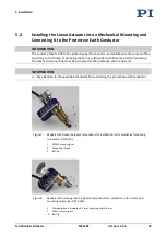
Figure 9: Example of the installation of two N-470.x10s on a mirror mount
1
N-470.x10 linear actuators with mounting thread
2
Mechanical mounting for linear actuators (fixed part of the mirror holder)
3
Mechanical mounting for mirror (movable part of the mirror holder)
Requirements
You have read and understood the general notes on installation (p. 17).
The N-470 is
not
connected to the electronics.
You have provided a suitable mechanical mounting (for dimensions of the linear
actuator see "Dimensions" (p. 44)):
−
The mechanical mounting must be connected to the protective earth conductor.
−
The contact surface of the mechanical mounting to the mounting nut or thread or
clamping shank of the N-470 must be electrically conductive.
−
The contact resistance at all connection points relevant for attaching the protective
earth conductor is <0.1 Ω at 25 A.
−
The contact surface of the mechanical mounting to the ball tip of the N-470 has a
roughness of R
a
<0.1 µm and a hardness of at least 500 HV.
−
For models with mounting thread: An M10×1 through-hole is in the mechanical
mounting.
−
For models with clamping shank: There is a through-hole with a suitable diameter in
the mechanical mounting.
You have accounted for the space required to route cables according to regulations and
without bending them.
Tools and accessories
Hook wrench (in the scope of delivery (p. 13))
When lubricant is to be applied to the contact surface of the moving part of the mechanical
mounting:
Models that are not suitable for use in a vacuum: PTFE-based grease containing no
additive
Vacuum-compatible models: Vacuum-compatible PTFE-based grease containing no
additive