10 Technical Data
M-230 Linear Actuators
MP102E
Version: 1.2
37
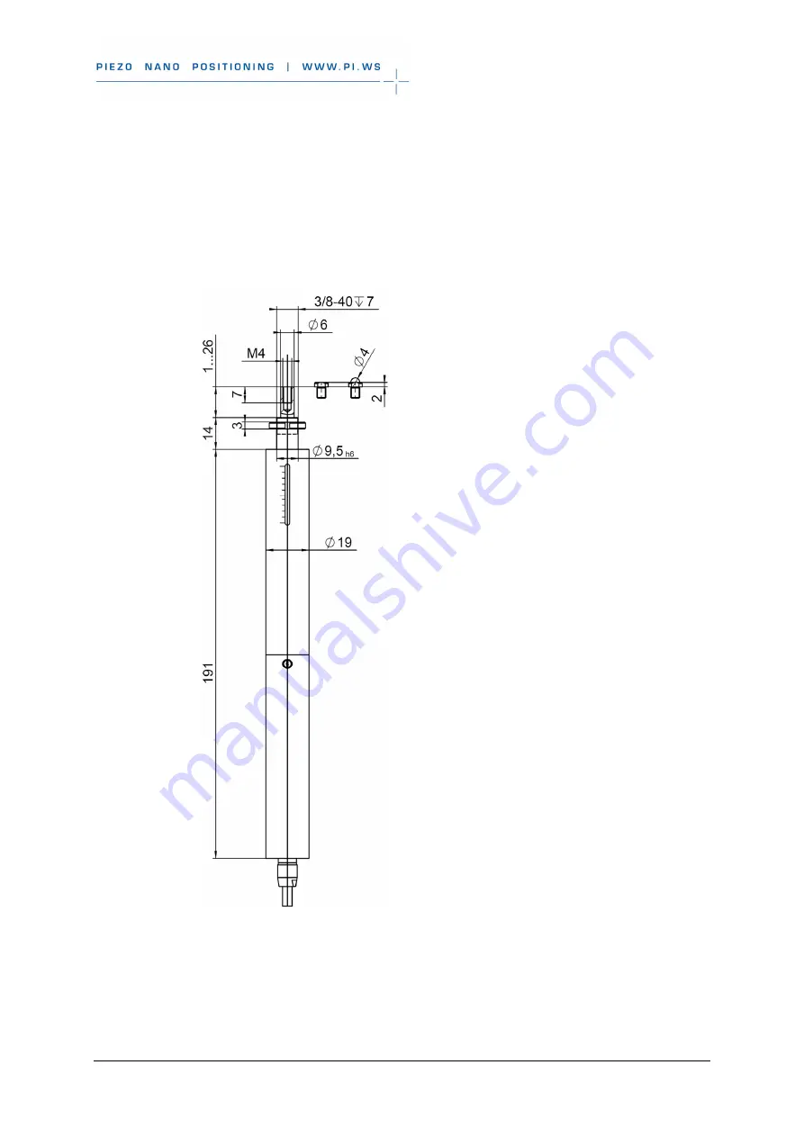
10.2.2 M-230.25, M-230.25S
Dimensions in mm. Note that the decimal places are separated by a comma in the drawings.
Figure 9: M-230.25, M-230.25S and M-230.25V, dimensions in mm
Page 1: ...Actuators User Manual Version 1 2 Date 31 08 2020 This document describes the following linear actuators with limit switches M 230 10 DC Drive 10 mm Travel Range High Resolution M 230 25 DC Drive 25...
Page 2: ...raphs and drawings in this manual are protected by copyright With regard thereto Physik Instrumente PI GmbH Co KG retains all the rights Use of said text photographs and drawings is permitted only in...
Page 3: ...easures during Installation 4 2 2 3 Safety Measures during Start Up 5 2 2 4 Safety Measures during Operation 5 2 2 5 Safety Measures During Maintenance 6 3 Product Description 7 3 1 System Overview 7...
Page 4: ...1 General Notes on Maintenance 27 7 2 Lubricating the M 230 27 7 3 Cleaning the M 230 27 8 Troubleshooting 29 9 Customer Service 31 10 Technical Data 33 10 1 Specifications 33 10 1 1 Data Table 33 10...
Page 5: ...load on our website 1 2 Symbols and Typographic Conventions The following symbols and typographic conventions are used in this user manual CAUTION Dangerous situation If not avoided the dangerous situ...
Page 6: ...oss reference to page 5 RS 232 Labeling of an operating element on the product example socket of the RS 232 interface 1 3 Other Applicable Documents The devices and software tools which are mentioned...
Page 7: ...Safety Instructions The M 230 is built according to state of the art technology and recognized safety standards Improper use can result in personal injury and or damage to the M 230 Only use the M 230...
Page 8: ...asures during Installation A cable break leads to a failure of the linear actuator Install the linear actuator so that the cable is not bent or squeezed too severely during operation Lateral forces th...
Page 9: ...at a safe distance from the motion range of the M 230 The collision of moving parts with the hard stop end of travel range as well as high acceleration can cause damage to or considerable wear on the...
Page 10: ...Settling time is too long If the performance of the M 230 is not satisfactory check the settings for the servo control parameters of your controller 2 2 5 Safety Measures During Maintenance The M 230...
Page 11: ...control equipment Loads configurations and control commands to the controller e g PC in connection with PC software PC software e g PIMikroMove included in the scope of delivery of PI controllers Con...
Page 12: ...tween the actuator and the load pusher with a separate tip depending on the model Also in case exchangeable parts can be used all options are included in the scope of delivery of the actuator e g tips...
Page 13: ...rive type Travel range Model Travel range Drive Type 10 mm 25 mm DC gearhead Stepper motor M 230 10 M 230 10S M 230 10V M 230 25 For further technical data see the specifications p 33 PI also produces...
Page 14: ...Figure 2 Product view M 230 with 25 mm left and 10 mm right travel range 1 Tip replaceable here flat 2 Mounting nut for clamp connection 3 Window with position display 4 Sleeve 5 Cable for connecting...
Page 15: ...0 linear actuators with PWM signals To order contact our customer service department p 31 3 8 Technical Features 3 8 1 Rotary Encoder The models with DC motors are equipped with a rotary encoder A rot...
Page 16: ...cated at about the midpoint of the travel range The reference point switch transmits an index pulse TTL when being passed In order to use the reference point switch signal for reference moves the cont...
Page 17: ...mpare the contents against the items covered by the contract and against the packing list 3 Inspect the contents for signs of damage If parts are missing or you notice signs of damage contact PI immed...
Page 18: ......
Page 19: ...on on the internal drive components Increased friction impairs the motion of the pusher and increases wear on the drive components Avoid lateral forces on the tip and on the pusher of the M 230 NOTICE...
Page 20: ...de area connection to a load A spherical tip allows a punctiform connection to a load To achieve optimum repeatability Use a tip Make sure that the selected tip is completely screwed in and does not h...
Page 21: ...ivery condition the pusher is extended far enough Tools and accessories Supplied tip Open end wrench SW 5 Figure 4 Changing the tip schematic 1 Flat tip with a wrench flat 2 Pusher non rotating 3 Moun...
Page 22: ...oviding a Suitable Mechanical Mounting and Installation Environment Figure 5 Relevant components and dimensions for installation in the mechanical mounting schematic 1 Mounting nut 3 8 inch 2 Mounting...
Page 23: ...load must not be inhibited by the dimensions of the installation environment Take into account the following specifications as well when planning the application and installing the actuator Dimension...
Page 24: ...the actuator and relevant individual parts can be found in the figures in the section Dimensions p 36 5 4 Installing the Linear Actuator in a Mechanical Mounting NOTICE Incorrect tightening torque of...
Page 25: ...You have read and understood the General Notes on Installation p 15 You have provided your application with a suitable mounting for the mounting shaft of the actuator Tools and accessories Supplied h...
Page 26: ...30 Linear Actuators 5 To clamp the actuator in the mounting tighten the mounting nut using the supplied hook wrench until you feel a resistance The torque must not exceed 1 7 Nm 6 Check that the actua...
Page 27: ...oller is connected Connecting a linear actuator to an unsuitable controller can cause damage to the linear actuator or controller Connect a linear actuator with DC motor to a DC motor controller only...
Page 28: ...use controllers and software from other manufacturers before starting up the actuator check the technical data to make sure that they are suitable INFORMATION The maximum velocity for a linear actuato...
Page 29: ...n cable to PC PC PC software for the controller for PI controllers included in their scope of delivery If necessary suitable motor cable from PI e g Motor cable C 815 38 3 m D Sub 15 m f Motor cable C...
Page 30: ...troller using the PC software for the used actuator see the user manual of the controller and the PC software If you use a PI controller select the entry in the stage database that precisely matches t...
Page 31: ...n a small travel range 20 of the entire travel range perform a maintenance run every 2000 motion cycles across the entire travel range Lubrication Under laboratory conditions the linear actuator needs...
Page 32: ...on 1 2 MP102E M 230 Linear Actuators Cleaning the linear actuator Do not use any organic solvents When necessary clean the surfaces of the linear actuator with a cloth slightly dampened with a mild cl...
Page 33: ...nation of motor controller and M 230 model p 25 Motor controller from a third party supplier Check the operating parameters The mechanical system does not move The cable is not connected correctly or...
Page 34: ...witches p 11 Limit switch is defective Motor controller ignores the limit switch signal 1 Stop the motor 2 Command the mechanical system away from the hard stop 3 Check the settings of the motor contr...
Page 35: ...ave questions concerning your system have the following information ready Product codes and serial numbers of all products in the system Firmware version of the controller if present Version of the dr...
Page 36: ......
Page 37: ...2048 cts rev Design resolution 0 0046 0 037 m typ Minimum incremental motion 0 05 0 1 m typ Backlash 2 2 m typ Unidirectional repeatability 0 1 0 1 m typ Velocity 0 8 1 2 mm s max Reference switch rep...
Page 38: ...g 5 Cable length 0 5 0 5 m 10 mm Connector D sub 15 m incl encoder driver D sub 15 m Recommended controllers drivers C 863 C 884 C 663 1 Max 0 25 A phase 24 full steps rev motor resolution with C 663...
Page 39: ...The signal logic depends on the model type Models with DC motor active high That means Normal motor operation low 0 V Limit switch reached high 5 V Models with stepper motor active low That means Nor...
Page 40: ...ion 1 2 MP102E M 230 Linear Actuators 10 2 Dimensions 10 2 1 M 230 10 M 230 10S Dimensions in mm Note that the decimal places are separated by a comma in the drawings Figure 8 M 230 10 M 230 10S and M...
Page 41: ...M 230 Linear Actuators MP102E Version 1 2 37 10 2 2 M 230 25 M 230 25S Dimensions in mm Note that the decimal places are separated by a comma in the drawings Figure 9 M 230 25 M 230 25S and M 230 25V...
Page 42: ...otor Connector Sub D 15 pin m Pin no Function 1 Internal 9 Input Motor 2 Input Motor 10 Internal 3 Internal 11 Internal 4 Input 5 V supply from controller 12 Output Limit switch signal negative side 5...
Page 43: ...1 Input Phase 1a 9 Input Phase 1b 2 Input Phase 2a 10 Input Phase 2b 3 Not connected 11 Not connected 4 Not connected 12 Not connected 5 Not connected 13 Not connected 6 Input 5 V supply from control...
Page 44: ......
Page 45: ...ternational national and local rules and regulations To meet the manufacturer s product responsibility with regard to this product Physik Instrumente PI GmbH Co KG ensures environmentally correct disp...
Page 46: ......
Page 47: ...12 EC Declaration of Conformity M 230 Linear Actuators MP102E Version 1 2 43 12 EC Declaration of Conformity...