phytron MCC-1 Manual Download Page 34

phytron


33 

 MA 1249-A009 EN 


  When the MCC-1 is connected to the PC by USB-interface, USB drivers 

have to be installed on the PC. You´ll find the driver on the delivered 
Phytron CD. 


  Administrator authorizations are required for the driver installation. 


  Only use an USB cable with a maximum length of 2 m! 


  Use the same USB Serial Port on the PC, when you want to check 

several USB Devices constructed in the same way. So the COM Port 
number won´t change. 


6.5.2  Ethernet Interface 

The MCC-1 

can be integrated into the firm’s network by the Ethernet adaptor.  

The port number of the MCC-1 controller is fixed to 22222 by Phytron. 


IMPORTANT: 


The controller obtains its IP address over DHCP exclusively. 
(dynamical IP configuration in every subnet)!  


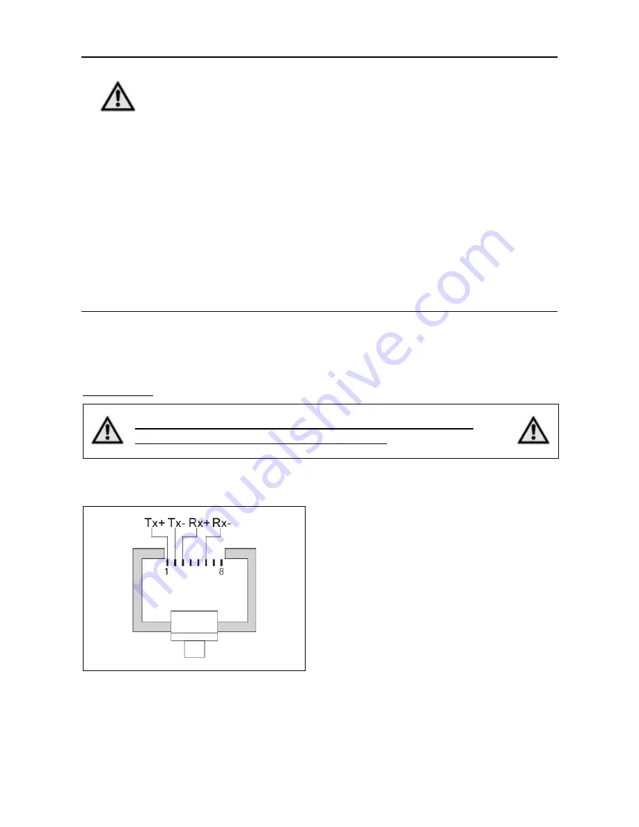
The Ethernet connection via RJ 45 connector (X5 Com):  


Abb. 1: 

X5: RJ 45 Ethernet connector  


Summary of Contents for MCC-1

Page 1: ...Extreme Precision Positioning MANUAL 1249 A009 EN Programmable Stepper Motor Controller for one Axis MCC 1...

Page 2: ...phytron 02 2019 Manual MA 1249 A009 EN MCC 1 Programmable Stepper Motor Controller for one Axis TRANSLATION OF THE GERMAN ORIGINAL MANUAL...

Page 3: ...cal manual All information contained in this manual is correct to the best of our knowledge and belief but cannot be guaranteed Furthermore we reserve the right to make improvements and enhancements t...

Page 4: ...Mechanical Installation 24 6 2 Electrical Installation 26 6 3 Connection of the Power Supply 26 6 3 1 X4 Power Supply I O 26 6 3 2 X9 Supply Voltage PWR 27 6 4 X8 Motor Connector 28 6 4 1 Stepper Mot...

Page 5: ...Stepper Motor Controller At the front side you ll find all connectors for wiring and assembling The MCC 1 housing contains mounting brackets for different mounting positions on the side and rear One o...

Page 6: ...iew of connectors X5 Com There are different connectors dependent on the built in PC interface card Please mention for all connector figures in this manual When the controller is placed in such positi...

Page 7: ...tor movements 1 2 2 Inputs and Outputs The MCC 1 controller has eight digital inputs and outputs electrically insulated and bidirectional The user defines by MiniLog software which pin is connected as...

Page 8: ...ice Green ready no error Read Error see status window in the MiniLog Comm software Orange Busy update of the indexer firmware You can select the controller s operating mode with the REMOTE LOCAL switc...

Page 9: ...Manual MCC 1 MA 1249 A009 EN 8 1 3 Block Diagram This block diagram shows a simplified layout You ll find details e g pin assignments in the corresponding chapters Fig 4 Block diagram...

Page 10: ...85 interface for wall mounting 10009857 with RS 485 interface for rail mounting 10009799 with RS 232 interface for wall mounting 10009859 with RS 232 interface for rail mounting 10009858 with USB conv...

Page 11: ...Cable connection A A 100 cm 10006880 USB cable connection A B 200 cm 10006881 USB 485 converter stick 10012292 Power supply unit SPH 240 4805 5 A 48 V for wall mounting 10015426 Power supply unit SPH...

Page 12: ...ompatibility 2014 30 EU applies to products which can cause electromagnetic interference or whose operation can be impaired by such interference The controller s compliance with the EMC Directive cann...

Page 13: ...Manual MCC 1 MA 1249 A009 EN 12 1 6 Declaration of Incorporation...

Page 14: ...l These persons should be able to recognize and handle risks emerging from electrical mechanical or electronic system parts The qualified personnel must know the content of this manual and be able to...

Page 15: ...accordance with the protective measures in chap 3 CAUTION Risk of damage by false motor current setting In case of motor voltages 24 V The controller must only be operated if the unit and the motor ho...

Page 16: ...the specified values of the corresponding chapters WARNING Danger of injury if touching the surface The surface of the MCC 1 reaches temperatures more than 75 C during operation The controller has to...

Page 17: ...rd and motor housing have to be grounded and or connected to 0 V Various options are possible to achieve the protective measure PELV Fig 6 PELV Grounding total Fig 7 PELV Grounding Power Stage and Mot...

Page 18: ...LV Grounding 0 V Protective measure PELV for application of the UB should not exceed 70 VDC or 50 VAC at dry environment environmental conditions 3 acc to IEC 61201 It is essential for MCC UB 48 VDC T...

Page 19: ...allic parts at a large area Good conductivity due to planar contacts Connect the housing via cable diameter more than 2 mm2 with potential equalisation Reduction of mutual interference Fit switching d...

Page 20: ...side of the cable should be fixed at the motor s earthing screw For EMC compliant wiring it is important to conductively connect the motor cable shielding mesh with the controller housing Use the cab...

Page 21: ...ed grounded on all sides Motor cable The length depends on the cable resistance Rcable 0 2x Rphase Dependent on the maximum current of the motor and the motor cable length is suitable 25 0 1 per 1 Amp...

Page 22: ...ide panels We recommend a vertical mounting labeling readable because of a better heat dissipation The clip for rail mounting is mounted on the rear side Accessories optional MCC 1 with attached USB c...

Page 23: ...m Winding inductance 0 5 to 10 mH per phase Phase current up to 3 5 APeak Step resolution 1 1 1 2 1 4 1 5 1 8 1 10 1 20 of a full step enhanced setting range up to 1 256 step for smoother motor run Ma...

Page 24: ...ror detection The MCC shuts down in case of undervoltage 17 V 1 V The error is set by the status bit and is indicated by the status LED which can be reset by a hardware or software reset power stage r...

Page 25: ...n two sides of the device allow different mounting positions The rail mounting clip is fixed with screws on the rear side The rap holes can also be used for individual mounting solutions on the rear s...

Page 26: ...phytron 25 MA 1249 A009 EN 1 Fig 12 Wall mounting MCC 1 dimensions Fig 13 Rail mounting MCC 1 dimensions...

Page 27: ...IC 2 5 4 G 5 08 IC 2 5 4 ST 5 08 10005390 X9 2 MSTB 2 5 2 GF 5 08 MSTB 2 5 2 STF 5 08 02005267 X10 5 FMC 1 5 5 G 3 5 FMC 1 5 5 ST 3 5 10006540 6 3 Connection of the Power Supply 6 3 1 X4 Power Supply...

Page 28: ...ide of the device For strain relief the cable should be fixed with one of the cable clamps at the bottom or the top side of the device Motor voltage is fused with 4 A fast DANGER Danger of electric ar...

Page 29: ...powered Fig 16 Motor connection to X8 connector Depending on application and stepper motor design other wiring modes are possible e g serial connected windings See next chap 6 4 2 WARNING Power stage...

Page 30: ...hytron 29 MA 1249 A009 EN 6 4 2 Wiring Schemes for 2 Phase Stepper Motors Fig 17 Wiring schemes for 2 phase stepper motors WARNING Motor leads not used should be individually isolated e g 6 lead motor...

Page 31: ...be fixed to the earthing screw below the MCC 1 motor connector The PE lead at the motor side of the cable should be fixed to the motor s earthing screw For EMC compliant wiring it is important to cond...

Page 32: ...the menu item Options Interface Parameters IMPORTANT If the MCC 1 is connected via Ethernet ensure that the IP address is created by DHCP dynamic IP configuration Differently generated IP addresses ar...

Page 33: ...rt it by double click The following window is shown on desktop after a successful installation Connect the MCC 1 directly or via USB converter to the USB port of your PC by USB cable For checking the...

Page 34: ...same USB Serial Port on the PC when you want to check several USB Devices constructed in the same way So the COM Port number won t change 6 5 2 Ethernet Interface The MCC 1 can be integrated into the...

Page 35: ...us connection to up to 16 MCC 1 Fig 22 Connection PC RS 422 485 interface MCC 1 RS 485 interface Remark It is not necessary to use an external bus termination connector for RS 485 bus because the bus...

Page 36: ...own in fig 16 or a converter which is installed on the first MCC 1 fig 17 must be inserted Fig 23 Bus Connection PC MCC 1 with USB RS 485 converter in RS 485 mode The MCC 1 type with installed USB RS...

Page 37: ...following figures point out the cable connections to a PC with RS 232 interface Depended on the type this can be a 9 pole or a 25 pole D SUB female connector RS 232 Connecting Cable PC MCC 1 Fig 26 P...

Page 38: ...g as joystick Enable This input is only analyzed by software see MiniLog Comm Specific information for processing the input signals you ll find in the programming manual MiniLog Comm Fig 28 X1 Pin ass...

Page 39: ...nction to control the movement in direction INI the second for the direction INI This type has the advantage that cable breaks can be recognized Mechanical opening limit switches can also be connected...

Page 40: ...Os are input or output can be defined by the user via MiniLog programming MiniLog instruction EASnnnnnnnn EAS instruction code n Allocation input or output n 1 input n 0 output Example EAS00000011 1 t...

Page 41: ...level Low 0 4 VDC Signal level High 20 30 VDC Fig 31 Input circuit diagram Outputs The overload safe outputs are equipped with protective diodes to protect the internal circuitry In the case of induc...

Page 42: ...he controller Use shielded cables twisted pair wise for encoder connection The transmission mode includes no protection against faulty transmission values Incremental encoder connection Absolute encod...

Page 43: ...t page CAUTION Danger of device damage Do not exchange X3 and X6 Danger of damage Connect the correct encoder type Do not parameterize an incremental encoder as SSI Wiring of Incremental Encoder or SS...

Page 44: ...tions Fig 36 X10 Connector Enable The Enable inputs A and B can be permanently activated by bypassing the inputs with the 24 VDC output This will work only if 24 VDC is supplied to the X4 connector Fi...

Page 45: ...Manual MCC 1 MA 1249 A009 EN 44 Fig 38 Enable Connector wiring...

Page 46: ...Active COM transmission protocol and baud rate The baud rate in the controller can be changed by clicking on A d v a n c e d and can be saved by S e t Baud rates MCC 1 can be selected in menu item Opt...

Page 47: ...eter the step resolution can also be set between full step and 1 256 step It is better to choose a high step resolution in most application situations because the motor will run more smoothly 6 After...

Page 48: ...r drive instructions into the window Drive relative The symbol or before the entered number of steps defines the direction When you click on the button S t a r t the instruction will be executed Now t...

Page 49: ...age MiniLog is welltried for editing sequential programs for machine controllers Complete sequential programs can be realized with MiniLog drive instructions initializing axes sub programs jump instru...

Page 50: ...inutes deactivation of the axes and measuring of the cooling behaviour Measurement at different run current values I 2 5 A and I 1 3 A The following heating curve defines the time constant of the MCC...

Page 51: ...raw the conclusion that these products are free of rights of third parties MiniLog Comm is a trade mark of the Phytron GmbH Microsoft is a registered trade mark and WINDOWS is a trade mark of the Micr...

Page 52: ...ental encoder 41 Input level 40 Inputs 36 39 Installation 13 Interface 6 L LabVIEW 48 LED 45 Limit switch 6 7 36 38 46 LOCAL 7 M MiniLog 48 MiniLog Comm 7 41 46 Ministep 6 Motor cable 30 Mounting clip...

Page 53: ...Supply voltage 22 Switch 7 SYNCHROCHOP 6 T Technical Data 22 Temperature 49 Touch voltage 17 Trade marks 50 U Undervoltage 23 USB 6 31 32 USB Driver 33 USB Port 32 USB driver 31 V Virtual instrument...

Page 54: ...Phytron GmbH Industriestra e 12 82194 Gr benzell T 49 8142 503 0 F 49 8142 503 190 www phytron eu...

Reviews: