3.4
Frame Grabber relevant Configuration
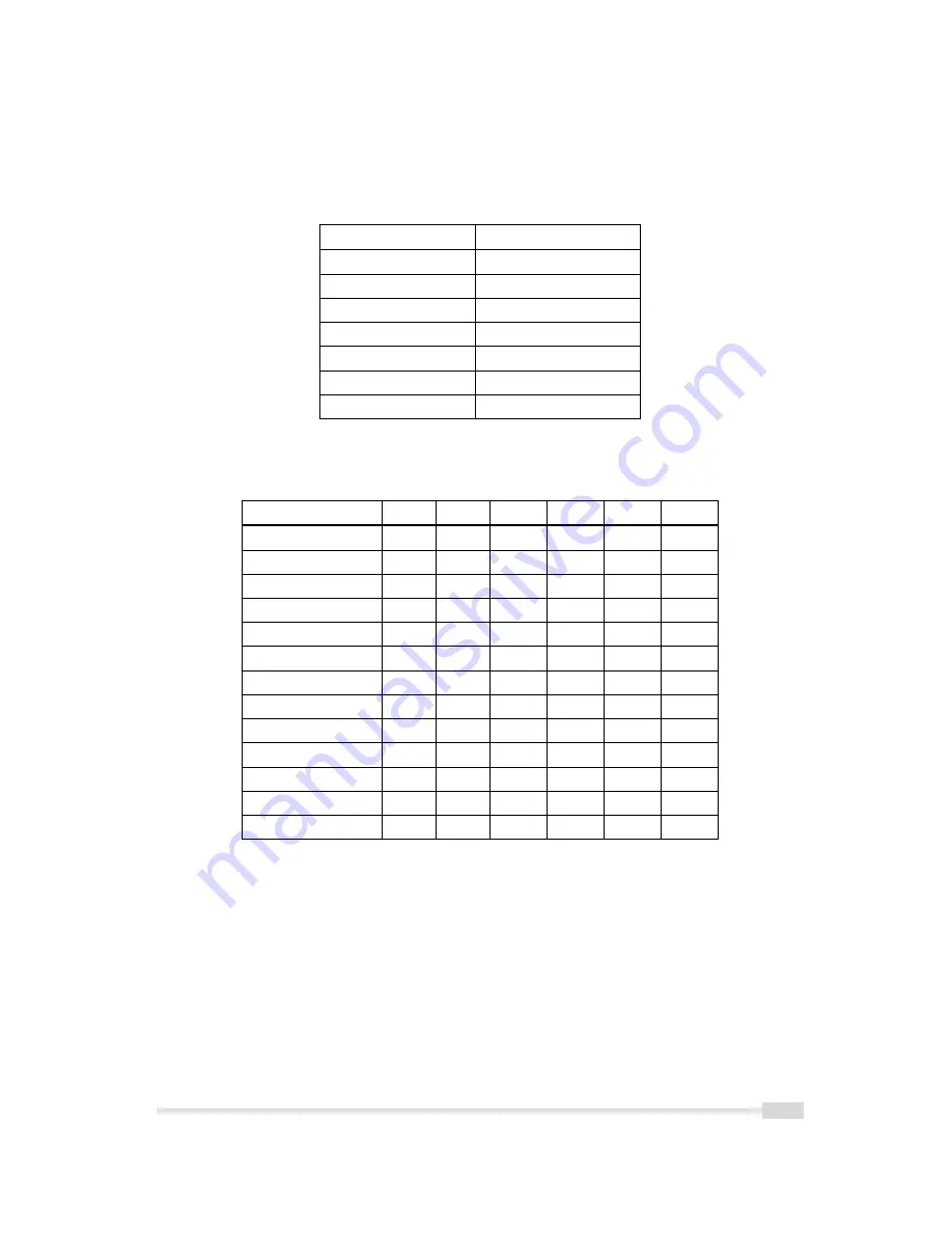
Table 3.5 summarizes the parameters needed for the configuration of the frame grabber.
MV-D1024E-3D01-160
Pixel Clock per Tap
80 MHz
Number of Taps
2
Greyscale resolution
12 bit / 10 bit / 8 bit
CC1
EXSYNC
CC2
not used
CC3
not used
CC4
not used
Table 3.5: Summary of parameters needed for frame grabber configuration
CameraLink Port and Bit assignments are compliant to the CameraLink standard (see [CL] ).
Bit
Tap 0
Tap 1
Tap 0
Tap 1
Tap 0
Tap 1
8 Bit
8 Bit
10 Bit
10 Bit
12 Bit
12 Bit
0 (LSB)
A0
B0
A0
C0
A0
C0
1
A1
B1
A1
C1
A1
C1
2
A2
B2
A2
C2
A2
C2
3
A3
B3
A3
C3
A3
C3
4
A4
B4
A4
C4
A4
C4
5
A5
B5
A5
C5
A5
C5
6
A6
B6
A6
C6
A6
C6
7 (MSB of 8 Bit)
A7
B7
A7
C7
A7
C7
8
-
-
B0
B4
B0
B4
9 (MSB of 10 Bit)
-
-
B1
B5
B1
B5
10
-
-
-
-
B2
B6
11 (MSB of 12 Bit)
-
-
-
-
B3
B7
Table 3.6: CameraLink port and bit assignments for the MV-D1024E-3D01-160 camera
The output of grey values is listed in Table 3.6. 3D data are assigned in the bits [7:0]. For
further information see Section 4.8.3.
.
3.4 Frame Grabber relevant Configuration
17
Summary of Contents for MV-D1024E-3D01-160
Page 1: ...User Manual MV D1024E 3D01 160 3D CMOS Camera MAN037 04 2009 V1 1...
Page 2: ......
Page 4: ...2...
Page 8: ...CONTENTS 6...
Page 20: ...3 Product Specification 18...
Page 57: ...5 2 CameraLink Data Interface 55...
Page 66: ...5 Hardware Interface 64...
Page 84: ...7 Graphical User Interface GUI 82...
Page 90: ...9 Warranty 88...
Page 92: ...10 References 90...
Page 96: ...A Pinouts 94...


