background image


Copyright © 2011, PHONO SOLAR 

                                  Page 5 of 29 

USER’S GUIDE 

 
AC Module Grid-Tie Inverter has been designed for many years of trouble free service.  Once 
installed, there are no user serviceable parts inside.  Please do not remove the covers or 
attempt to perform any service unless you are fully qualified to do so. 
 
AC Modules operate silently, with no moving parts.  If you suspect a AC Module is not 
operating properly, please contact your installing dealer or other qualified service personnel 
for assistance. 
 
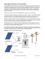
The “HelioSentry

®

” is the monitoring system for your PV system. It displays various operating 

data for each AC Module in your system.  The HelioSentry

®


is 802.11g “Wi-Fi” compatible.  It 

will allow the user to monitor and commission the PV array via a home computer or laptop PC.  
See the HelioSentry

®


User‟s Manual for additional information.   


NEED-TO-KNOW TERMS 

  AC -  Alternating current 

  DC 

– Direct Current 

  PV 

– Photovoltaic 

  AC Module 

– DC to AC inverter circuitry(black box mounted on the rear of the AC 

Module) 

  Array 

– A group of AC Modules 


PRODUCT OVERVIEW 


PHONO SOLAR‟s AC Module is a solar panel that produces utility-ready AC power that can 
be  either  consumed  on  the  premise  or  fed  back  into  the  electric  utility  network.    Standard 
solar  panels  produce  DC  power  and  require a  central inverter  to  convert  DC  to  AC.   When 
more  power  is  generated  than  consumed,  you  will  have  what  is  referred  to  “net  metering”, 
where  your  electric  meter  will  actually  spin  backwards  and  you  may  receive  monetary  or 
other credit for the power fed into the utility grid.  

The PHONO SOLAR’s AC Module shall be connected only to a 120VAC, 60Hz dedicated 
branch circuit. 


HelioSentry

®

 is a trademark of EXELTECH, Fort Worth, Texas 

Summary of Contents for PS240 M- 20/U

Page 1: ...d This Document may not be copied photocopied reproduced translated or converted to any electronic or machine readable form in whole or in part without prior written approval of PHONO SOLAR Product Sp...

Page 2: ...direct incidental or consequential damages under any circumstances No oral or written information or communications given by PHONO SOLAR or its employees or agents shall alter the scope of this discla...

Page 3: ...ath or serious injury and or damage to equipment and property CAUTION Indicates a potentially dangerous situation that may result in minor or moderate injury May also be used to alert against unsafe p...

Page 4: ...the units The ground wire at the service entry should be 14 AWG copper or larger or sized as appropriate within your local jurisdiction electrical code If uncertain check with your local code enforcem...

Page 5: ...a home computer or laptop PC See the HelioSentry User s Manual for additional information NEED TO KNOW TERMS AC Alternating current DC Direct Current PV Photovoltaic AC Module DC to AC inverter circui...

Page 6: ...40 C to 70 C Output power temperature derating and maximum full power operating ambient temperature 212 watts out 50 C Derated by the PV above 50 C CEC and Peak Inverter Efficiency 94 5 CEC 95 8 peak...

Page 7: ...ers IEEE 1547 and 1547 1 Safety Standard for Utility Interactive Inverters IEEE 929 Recommended Practice for Utility Interface of Photovoltaic PV Systems IEEE 519 Harmonic Standard Surge ANSI C62 41 B...

Page 8: ...ONOSOLAR DC MODULE SPECIFICATION Cells Mono crystal Si 156mm x 156mm square Number of cells 6x10 pieces in series Typical application 20V DC Maximum voltage 600V DC Size 1640 L x992 W x50 H mm Weight...

Page 9: ...S Cable 0 90m wire 4mm2 Diode s amount 6 pieces Junction Box IP 65 rated ELECTRICAL TYPICAL VALUES1 2 Model Rated Power PMPP Toleran ce Rated Current IMPP Rated Voltage VMPP Short Circuit Current Isc...

Page 10: ...DC solar panels AC modules eliminate most of the issues associated with ordinary DC string inverter systems AC modules are much easier to install Lower cost to install Far less prone to shading and ot...

Page 11: ...r package and the contents for signs of damage If there is shipping damage contact the carrier and return the unit to the factory Record the 15 digit PV Module ID number indicated on the front of the...

Page 12: ...The installer would need to perform a calculation to determine the number of inverters versus the total cable length The AC Module may be mounted in any orientation See Figure 2 The location selected...

Page 13: ...made of durable corrosion and UV resistant material 1 Mounting With Bolts The frame of each module has 8 mounting holes 14mm 9mm used to secure the modules to supporting structure The module must be a...

Page 14: ...block the air flow path NOTE Minimum clearance distances must be observed if your AC Module inverter system is to operate at maximum rated output in hot weather NOTE Any mounting location that restri...

Page 15: ...structions as specified and in the order presented CAUTION Ensure AC conductors have no voltage present Open all AC circuit breakers and verify zero volts are present before proceeding NOTE Use only t...

Page 16: ...s own AC 20 ampere disconnect breaker NOTE The combined output power of multiple inverters may not exceed the service rating of the circuits to which the inverters are connected Consult ANSI NFPA 70 T...

Page 17: ...utral The GREEN insulated conductor is protective earth ground The neutral conductor must be bonded to earth ground at your service entry See Figure 4 Secure the Home Run cable from the last AC Module...

Page 18: ...ength is adequate to reach all modules and the HelioSentry 2 Attach the AC quick connectors to the home run wire See steps1 10 below Space the connections evenly across the modules 3 Secure the home r...

Page 19: ...CABLE STEP 1 Loosen the screws from the connector STEP 2 Separate upper and lower sections of connector CAUTION Failure to secure the Home Run cable as required could cause fraying of the insulation o...

Page 20: ...Copyright 2011 PHONO SOLAR Page 20 of 29 STEP 3 Inspect silicone gasket STEP 4 Reseat silicon gaskets back into both sections of connector STEP 5 Verify AC wire to connector orientation...

Page 21: ...onnector onto AC wire STEP 7 Align upper and lower halves of connector Before securing connector verify alignment by observing to ensure connector teeth penetrate the outer jacket Visually verify the...

Page 22: ...n when tightening like a car tire Tighten screws snugly and uniformly Do not over tighten STEP 9 Verify the screws are tightened correctly by inspecting both sides of connector Upper and lower sides o...

Page 23: ...one end of connector CORRECT No gaps between upper and lower sections of connector STEP 10 Verify all connectors are have the same orientation connector pigtails are facing the same way WARNING FAILU...

Page 24: ...SOLAR Page 24 of 29 DAMAGE TO THE HELIOSENTRY DATA MONITOR This completes the installation of your AC Module s The system is now ready for the commissioning steps Figure 4 is a representative wiring d...

Page 25: ...rod Electrical codes typically require this to be a one piece agency approved compression connector Agency approved means Nationally Recognized Testing Laboratories such as ETL UL TUV and others The g...

Page 26: ...n one PV rack ground lug Insert the remaining end of the ground wire in the other lug Tighten both ground lug compression screws to 12 inch lbs Repeat the above steps for subsequent PV rack mounts NOT...

Page 27: ...t at least 5 minutes Power production will commence five minutes after connection is established to the utility grid provided there is sufficient power available from the photovoltaic modules This fiv...

Page 28: ...st be performed by qualified service personnel only CAUTION Some of the components inside the AC Module will store a high voltage charge for several minutes after DC and AC power is removed Take all n...

Page 29: ...enclosure Torque to 10 inch pounds DO NOT OVERTIGHTEN 12 Reinstall the PV module onto the rack 13 Verify that all hardware is tight per the installation instructions 14 Restore AC power to the AC Modu...

Reviews: