background image

UM 30/31/40/41/50/51

9

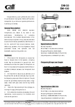
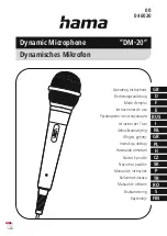
2. Receiver Module (UM-R10 and UM-R11�

This  receives  the  RF  signal  sent  from  the 

bodypack  transmitter.  The  UM-R10  has  four 

LED  indicators:  two  RF,  one AF  and  a  Power 

indicator. The UM-R11 simply has 1 for Power.

I. Power indicator

This  LED  will  illuminate  when  the  receiver 
module receives power.
  

II. RF LED Indicators

When  one  of  these  LEDs  is  illuminates,  it 
indicates  that  the  bodypack’s  signal  is  being 
received successfully.  The RF LED that lights 
up  is  determined  by  whichever  antenna  is 
receiving a clearer signal from the transmitter. 
If for some reason this LED does not turn on, 
check  your  batteries  in  the  transmitter  and 

configuration and try again.

III. AF LED Indicator

AF LED Indicator

F LED Indicator

When  this  LED  is  illuminated,  it  indicates 
that  there  is  an  audio  signal  present.    If  this 
LED  is  not  activated,  check  the  head  of  the 
microphone  is  correctly  attached,  and  double 
check your set up.

IV. Channel Selector

Channel Selector 

This  indicates  the  channel  number  that  is 
actually  in  use  by  the  receiver.  This  number 
should be identical to the channel selected on 
the transmitter.

V. Volume Control

Volume Control

 Control

Control

This  dial  determines  the  audio  level  of  the 

signal received by the UM-R10 receiver. 

3.Condenser Lavaliere Microphone (ML-10�

Lavaliere microphones are widely used in broad

-

casting  and  also  for  personal  presentations. 
Its  small  size  make  them  perfect  for  any  pro

-

fessional  application,  also  you  will  save  space 
and efforts. This is a condenser microphone, it 
means  that  needs  voltage  to  proper  function, 
this  will  be  feed  from  the  bodypack  batteries, 
and this also gives you a great signal gain.

4.Condenser Headset Microphone (MH-20�

The headset microphone is a very comfortably 

fitting  microphone  that  sits  perfectly  on  your 

head.  Brings  you  freedom  of  movement,  this 
way you can do all your activities while you are 
speaking at the mic.

UM-R11

UM-R10

Summary of Contents for UM 30

Page 1: ...UM 30 31 40 41 50 51 User s Manual Manual del Usuario UM30 31 40 41 50 51 Wireless Microphone System Micr fono Inal mbrico English Espa ol...

Page 2: ...19 INSERCI N DE BATER A 21 I N S TA L A N D O E L M O D U L O RECEPTOR 22 ESPECIFICACIONES 23 CONTENIDO 26 26 26 27 UM30 UM31 28 UM40 UM41 UM50 UM51 30 32 33 34 Phonic preserves the right to improve o...

Page 3: ...V DSSDUDWXV GXULQJ OLJKWLQJ VWRUPV RU ZKHQ XQXVHG IRU ORQJ SHULRGV RI WLPH 5HIHU DOO VHUYLFLQJ WR VHUYLFH SHUVRQQHO 6HUYLFLQJ LV UHTXLUHG ZKHQ WKH DSSDUDWXV KDV EHHQ GDPDJHG LQ DQ ZD VXFK DV SRZHU VXS...

Page 4: ...CE 16 selectable UHF channels preset Oscillation mode Microprocessor controlled PLL synthesized Receiving Mode Diversity Internal squelch and mute circuit mode that can resist unusual noise SAW filte...

Page 5: ...l frequency on the hand held or bodypack so you can start transmit ting to the receiver 3 Make sure that you have selected the same channel number on the receiver as the handheld mic or bodypack If no...

Page 6: ...ers can select from 16 different frequency channels with this selector This comes handy if users find problems with the frequency allocations If you find noise problems on your audio or if your audio...

Page 7: ...by whichever antenna is receiving a clearer signal from the transmitter If for some reason this LED does not turn on check your batteries in the transmitter and configuration and try again III AF LED...

Page 8: ...er is not obstructed at all IV LED Indicator When the power switch is in the ON position this LED will be illuminated in green If this LED doesn t turn on or light up in red your batteries will need t...

Page 9: ...the head of the microphone is correctly attached and double check your set up IV Channel Selector This indicates the channel number that is actually in use by the receiver This number should be ident...

Page 10: ...ase clockwise to refasten Ensure the handheld mic is firmly together Bodypack Transmitter 1 On the back of the bodypack you will find the battery cover Gently remove it by sliding it down 2 Insert two...

Page 11: ...the grounding PCB from the golden finger socket Insert the UM R11 re ceiver into the module compartment and use a screw to secure it into place Replace the com partment cover Powerpod 865 and 885 Plus...

Page 12: ...red LED for power Control UM R10 Output Volume Channel Selector UM R11 Channel Selector AF Output Impedance 600 Unbalanced Squelch Pilot Tone Noise Mute Operation Voltage 6 8 VDC 500 mA Output connec...

Page 13: ...0 Type Lavaliere Headset Frequency Response 100 Hz 13kHz 50Hz 18 kHz Polar Pattern Cardioid Cardioid Sensitivity at 1 kHz 70 dB 3dB 70 dB 3dB Impedance 2 2k ohms 30 680 ohms 30 Max SPL for 1 THD 130dB...

Page 14: ......

Page 15: ...suario Modalidad de Oscilaci n Microprocesador controlado por PLL sintetizado Modalidad de recepci n Diversity Circuitos internos de Squelch y Mute que pueden resistir ruido inusual Filtros SAW para r...

Page 16: ...la frecuencia de canal en tu handheld o bodypack de tal manera que puedas transmitir al receptor 3 Aseg rate de que has seleccionado el mismo n mero de canal en el receptor ya sea el micr fono de man...

Page 17: ...rtimiento III Selector de Canal Los usuarios pueden seleccionar de entre 16 diferentes canales de frecuencias con este selector Esto viene muy til si los usuarios encuentran problemas con las frecuenc...

Page 18: ...xitosamente El LED de RF determina qu antena esta recibiendo una se al clara del transmisor respectivamente Si por alguna raz n este LED no se enciende revisa tus bater as y tu configuraci n e intente...

Page 19: ...i n ON este LED ser iluminado en verde Si esto no sucede o se ilumina en rojo necesitaras cambiar tus bater as Cuando se ilumina en rojo significa que la bater a est bajo V Compartimiento de las Bater...

Page 20: ...evisa nuevamente tu configuraci n IV Selector de Canal Este selector indica que canal esta siendo utilizado por el receptor El n mero deber de ser id ntico al canal del transmisor V Control de Volumen...

Page 21: ...manecillas del reloj para reinstalarlo Aseg rate de que el micr fono esta firmemente unido Transmisor Bodypack 1 En la parte trasera del bodypack encontraras una cubierta de las bater as Ret rala gent...

Page 22: ...kets Inserta el receptor UM R11 dentro del compartimiento del m dulo y utiliza un destornillador para asegurarlo en su lugar Coloca nuevamente la cubierta Powerpod 865 y 885 Plus Abre el compartimient...

Page 23: ...AF UM R11 LED rojo para encendido Control UM R10 Volumen de salida Selector de Canal UM R11 Selector de Canal Impedancia de Salida de AF 600 ohms desbalanceada Squelch Tono Piloto Cancelaci n de Ruid...

Page 24: ...W Micr fono Lavaliere Diadema Headset Numero de modelo ML 10 MH 20 Tipo Lavaliere Headset Respuesta en Frecuencia 100 Hz 13kHz 50Hz 18 kHz Patron polar Cardioide Cardioide Sensibilidad 70 dB 3dB 70 dB...

Page 25: ...CAUTION RISK OF ELECTRIC SHOCK DO NOT OPEN PHONIC CORPORATION...

Page 26: ...pod 865 885 Plus 614 175 804 800 MHz FCC 614 175 864 800 MHz CE 16 UHF PLL SAW RF Sound Ambassador UM30 HT 100 UM R10 UM40 ML 10 BT 200 UM R10 UM50 MH 20 BT 200 UM R10 RoadGear Performer Powerpod Plus...

Page 27: ...UM 30 31 40 41 50 51 27 ML 10 MH 20 ML 10 XLR XLR MH 20 XLR XLR 1 2 3 4 5 RF AF LED LED 6...

Page 28: ...UM 30 31 40 41 50 51 28 UM30 UM31 UHF 1 HT 100 LED I II 1 5V AA III 16 IV LED LED V LED HT 100...

Page 29: ...UM 30 31 40 41 50 51 29 UM R11 UM R10 2 UM R10 UM R11 RF UM R10 4 LED RF LED AF LED LED UM R11 I LED II RF LED LED RF LED LED III AF LED LED LED IV V UM R10...

Page 30: ...UM 30 31 40 41 50 51 30 UM40 UM41 UM50 UM51 1 BT 200 I MH 20 ML 10 II III IV LED V 1 5V AA VI VII VIII...

Page 31: ...UM 30 31 40 41 50 51 31 UM R11 UM R10 2 UM R10 UM R11 RF UM R10 4 LED RF LED AF LED LED UM R11 LED I LED II RF LED LED RF LED LED III AF LED LED LED IV V UM R10 3 ML 10 4 MH 20...

Page 32: ...UM 30 31 40 41 50 51 32 1 2 3 1 5V AA 4 1 2 1 5V AA 3 DC...

Page 33: ...UM 30 31 40 41 50 51 33 UM31 41 51 Performer Performer PCB UM R11 RoadGear 120 160 260 RoadGear UM R11 Powerpod 865 885 Plus UM R11 UM30 40 50 Sound Ambassador 75 120 Deluxe 2 PCB UM R10...

Page 34: ...0M UM R10 UM R11 True Diversity 0 005 100 dB RF 100 dBm 75 dB 0 5 1KHz LED UM R10 LED A B LED AF UM R11 UM R10 UM R11 AF 600 6 8V DC 500 mA x x 61 x 25 x 123 mm HT 100 BT 200 60 dBc 60 dBc 0 005 0 005...

Page 35: ...UM 30 31 40 41 50 51 35 ML 10 MH 20 100 Hz 13 kHz 50 Hz 18 kHz 1kHz 70 dB 3dB 70 dB 3dB 2 2k 30 680 30 SPL 1 130 dB 130 dB XLR XLR...

Page 36: ...ZZ SKRQLF FRP VXSSRUW Kt SRGUi HQFRQWUDU UHVSXHVWDV D ODV SUHJXQWDV PiV IUHFXHQ WHV FRQVHMRV WpFQLFRV GHVFDUJD GH GULYHUV LQVWUXF FLRQHV GH GHYROXFLyQ GH HTXLSRV PiV LQIRUPDFLyQ GH PXFKR LQWHUpV 1RVRW...

Reviews: