


Performer User's Manual PHONIC CORPORATION
page 8
PHONIC CORPORATION Performer User's Manual
page 9
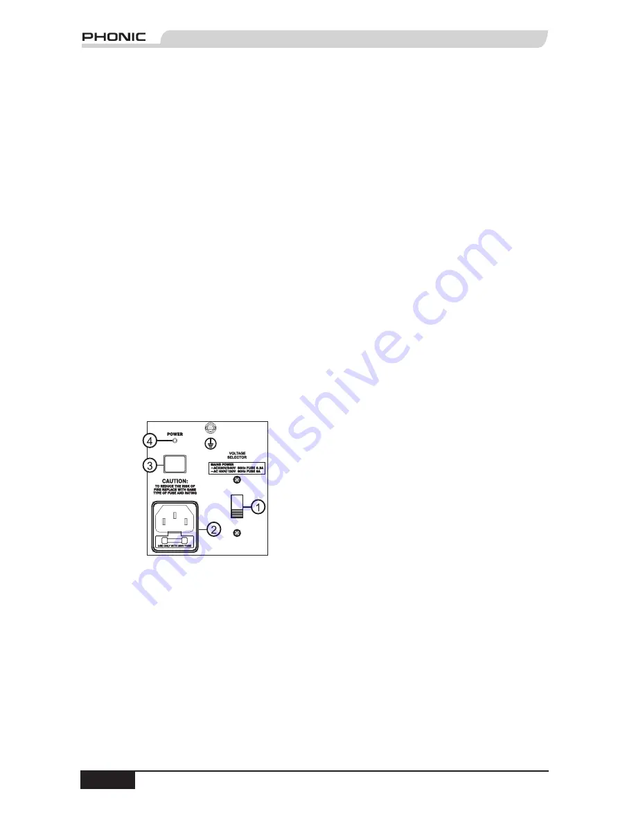
REAR PANEL DESCRIPTION
1. VOLTAGE SELECTOR
This switch allows you to select the AC electric
current in use in your region. It is very important
that you select the correct MAINS POWER voltage
before plugging in the power cord. For 220-240
volts 50 Hz, push the switch up. For 110-120 volts
60 Hz, push the switch down. Voltage levels vary
from country to country, (even from city to city in
certain countries). For example, North America
uses a 110-120 volt, 60-cycle (Hz) system, while
the European standard is 220-240 volt, 50-cycle
(Hz).
Note:
The U.S. Department of Commerce's International
Trade Administration produces a very useful publication
called "Electric Current Abroad." It is an exhaustive list of
the electric current characteristics of every country (and its
cities, if there is variance) and the type of AC plugs in use
in those countries.
2. IEC Socket
Connect the supplied AC power cord here. Since
Performer active speakers have built-in power
amplifiers, you must connect them to an AC power
supply or you won't get any sound.
Note:
If you happen to leave the power cord behind at a
gig, don't worry. The 3-pin plug with ground pin is readily
available at most office and computer supply stores.
3. POWER Switch
To turn on the Performer active speaker set the
POWER switch in (down). To turn off the Performer
set the switch out (up). Make sure the volume
control is all the way down before you turn the
power on or off.
4. POWER On Indicator
This LED indicator is located just above the
POWER switch. When the POWER is on and
the Performer is connected to an active AC Mains
supply, this indicator glows.
5. LOW CUT
This switch engages or disengages the low cut
filter. Turn on the low cut filter by setting the switch
in (down). To turn it off set the switch out (up).
The low cut filter cuts out frequencies below the
75 Hz range. It is especially useful for eliminating
unwanted noise like stage rumble, P-pops and
wind noise. It's also a good idea to use the low
cut filter when using the Performer as a stage
monitor.
6. CONTOUR
Use this feature when working in live sound
applications. Pushing in the switch gives a 5 dB
boost to frequencies below 80 Hz and above 10.5
KHz, making your highs clearer and giving your
bass more kick. Try out the sound with the contour
switch in and out to see which sounds best for your
application.
7. WIRELESS/WIRELESS MIC Switch
This switch allows you to select between
the different types of wireless signals being
transmitted to the Performer active speaker. To
select the wireless microphone, first ensure that
the correct wireless module is installed, and then
set the switch out (up). To select a wireless signal
coming from another wireless source, such as
a wireless mixer transmission module or from
another Performer active speaker, ensure that the
correct wireless module is installed, and then set
the switch in (down). (For more information about
wireless microphones and modules, please refer
to page 16.)
8. Signal Indicator (Wireless)
After selecting WIRELESS or WIRELESS MIC,
this LED lights up whenever the selected signal
is present.
9. Wireless Volume Control
Use this rotary control to set the volume level
for the wireless input signal. It's a good idea to
first turn the volume control all the way down
(counterclockwise). Turn on the selected source
signal and then slowly turn up the volume control
until you reach the desired volume level (but not
until the PEAK indicator lights up).
Note:
If you are not using the wireless function of this
speaker, it is best to turn the volume all the way down to
avoid picking up any radio frequency interference.
10. PEAK Indicator (Wireless)
This LED illuminates when the signal levels at the
amplifier outputs approach clipping. It's OK for the
PEAK indicator to blink infrequently, but if it blinks


