iA231F / iA231FD User's Manual
PHONIC CORPORATION
page 6
page 7
PHONIC CORPORATION
iA231F / iA231FD User's Manual
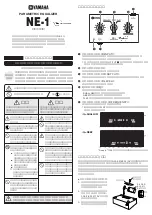
Back Panel
12. Power Switch
This switch simply turns the iA equalizers on and off.
13. Power Input and Fuse
Power is supplied via an IEC standard 3-pin connector.
The power supply fuse is located in a fuse holder fitted
into the rear panel. Always replace with the correct type
and rating of fuse, as indicated adjacent to the fuse
holder.
14. S/PDIF Input and Output (iA231FD only)
These RCA S/PDIF jacks are for the input and output
of digital signals, allowing audio to be passed from one
device to another without having to convert the signal
from digital to analog and back again. To use the S/PDIF
inputs, the Input Select switch must be set to allow the iA
equalizer to accept the signal. The output sampling rate
is selected using the Output Select switch. This feature
is available on the iA231FD only.
15. Sampling Rate Switch (iA231FD only)
This switch allows users to adjust the output sampling
rate of the S/PDIF output between 44.1 kHz, 48 kHz
and 96 kHz per second. This feature is available on the
iA231FD only.
16. Input Select Switch (iA231FD only)
By using this switch, users can adjust the input of the
iA equalizer between that of the Analog inputs and that
of the Digital inputs.. This feature is available on the
iA231FD only.
17. AES Input and Output (iA231FD only)
These XLR AES/EBU (also known as AES3) standard
input and output connectors can be used to receive and
send digital signals to and from various digital signal
processors, recorders and other products that feature
digital interface abilities.. This feature is available on the
iA231FD only.
18. Subwoofer Output and X-Over Control
The 3-pin XLR output is for the output of low frequency
sounds, suitable for use in conjunction with subwoofer
speakers. The subwoofer crossover frequency can be
selected between 20 to 250 Hz by the small control
located next to the output.
19. Analog Inputs and Outputs
The female XLR inputs are for the addition of external
analog signals to the iA equalizers, whereas the 3-pin
XLR outputs are for the connection of external devices
to receive the equalized signal. There are also input
and output operating level switches, which allow users
to adjust the iA equalizer to suit either pro and semi-
pro audio equipment, as well as consumer level audio
products. Set at +4 dBu for professional audio products,
and -10 dBV for consumer products.
Summary of Contents for IA231F
Page 10: ...iA231F iA231FD User s Manual PHONIC CORPORATION page 10 FREQUENCY CHART...
Page 14: ......
Page 15: ......
Page 16: ......