iA231F / iA231FD User's Manual
PHONIC CORPORATION
page 6
page 7
PHONIC CORPORATION
iA231F / iA231FD User's Manual
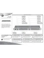
Front Panel
1. LED Indicators
With two colors and 8 segments; the LED indicators
visually represent the output level of the equalizer.
The clip button indicates when the input (or output, as
designated by the I/O Meter button) signal is too high,
and is dynamically clipped as to protect the internal
circuitry.
2. Range Button
Selects maximum cut or boost for the equalizer of either
6 dB or 12 dB, and the indicator will light up to show
you which level range you are using. The 12 dB settings
should be used when much equalization is needed; the
6dB setting allows for finer adjustments on the frequency
levels.
3. EQ IN/OUT Switch
Push this button in to add the equalizer into the signal
path, push again to raise the button and remove the
equalizer section from the signal path. This switch does
not defeat the low or high cut filters.
4. Input Level Control
Turn this knob to adjust the input level from -
∞
dB to
+15 dB.
5. I/O Meter Button
This button allows users to alternate the use of the
LED level meter between the input and output signals.
When pushed in, the level meter will give users a
clear representation of the input signal, whereas when
the button is released, the output signal will then be
analyzed instead.
6. Feedback Detection Button
Pushing this button activates the built-in feedback
detection system of he iA equalizer. Frequencies with
the potential for creating feedback are indicated by
flashing LEDs on each frequency’s VR fader.
7. Low Cut Control
This knob enables a subsonic filter range from 15 Hz to
400 Hz. Its function is to "roll off" the response below a
given frequency to eliminate subsonic interference like
wind noise, stage rumble, and microphone "pop". This
function, independent of EQ IN switch, is disabled when
set to the OFF position.
8. High Cut Control
This knob enables a super-to-ultra-sonic filter range
from 2.5 kHz to 25 kHz. Its function is to "roll off" the
response above the selected frequency to eliminate
high frequency interference, unwanted noise and hiss
that may be present at high frequencies. This function,
independent of EQ IN switch, is disabled when set to the
OFF position.
9. Limiter Control
This control is used to select the threshold of the iA
equalizer's built-in limiter. It allows users to adjust the
limiter from -20 to +10 dBu, or turn it off all together.
10. Link Button
By pushing this button, any settings made to channel
1 are applied to channel 2. This is helpful so that when
stereo signals are sent through channels 1 and 2 of the
iA equalizer it is not necessary to set both channels'
faders.
11. Faders
Smooth operation with center detent and accurate flat
setting, these faders allow users to boost or cut their
signal’s various frequencies by up to 12 dB. If the Range
button is pushed in, the level of boost and cut is then 6
dB.
CONTROLS AND SETTINGS
Summary of Contents for IA231F
Page 10: ...iA231F iA231FD User s Manual PHONIC CORPORATION page 10 FREQUENCY CHART...
Page 14: ......
Page 15: ......
Page 16: ......


