background image

MACX MCR-CONF

2-4

PHOENIX CONTACT

104203_en_03

2.3

Tabs

2.3.1

Device Settings

The "Device Settings" tab contains configuration and parameterization dialog boxes that 

are relevant for the connected device. 

The tree structure is divided into the following groups:

Device descriptor

Configuration

Parameterization

Service

In all windows in which parameters can be modified: 

The modified parameters are indicated with an icon (pencil)

The "Cancel" button is available to reject the current changes

If a yellow padlock appears in front of the menu items in the tree structure, these menu 

items are locked. To unlock them, enter a password via the "Service" menu item 

(see page 2-8).

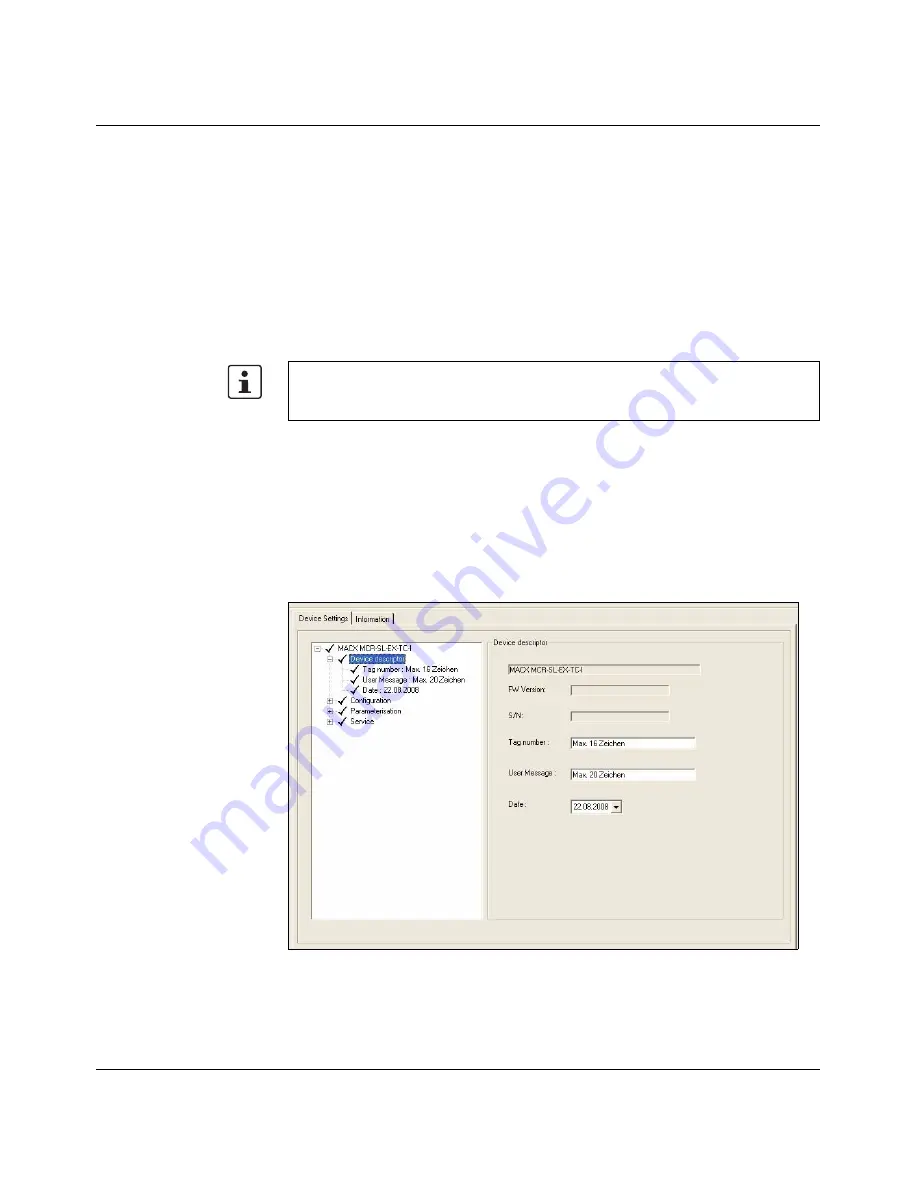
Device descriptor

A device designation (16 characters), user text (20 characters, 

maximum), and the installation date can be specified here.

In addition, the module name, serial number, and firmware 

version are displayed.

Summary of Contents for MACX MCR-CONF

Page 1: ...INTERFACE UM EN MACX MCR CONF User Manual Quick Start Guide for the MACX MCR CONF configuration software ...

Page 2: ......

Page 3: ...is user manual is valid for INTERFACE 104203_en_03 PHOENIX CONTACT 2009 12 08 Quick Start Guide for the MACX MCR CONF configuration software UM EN MACX MCR CONF 03 Designation Version Order No MACX MCR CONF 1 1 7 or later User Manual ...

Page 4: ...l Explanation of symbols used and signal words The following types of messages provide information about possible property damage and general information concerning proper operation and ease of use This is the safety alert symbol It is used to alert you to potential personal injury hazards Obey all safety messages that follow this symbol to avoid possible injury or death DANGER This indicates a ha...

Page 5: ...rrors in the information cannot be ruled out Phoenix Contact does not offer any guarantees as to the reliability accuracy or completeness of the information All information made available in the technical data is supplied without any accompanying guarantee whether expressly mentioned implied or tacitly assumed This information does not include any guarantees regarding quality does not describe any...

Page 6: ...Windows 95 Windows 98 Windows NT Windows 2000 Windows XP and Windows Vista are trademarks of the Microsoft Corporation All other product names used are trademarks of the respective organizations How to contact us Internet Up to date information on Phoenix Contact products and our Terms and Conditions can be found on the Internet at www phoenixcontact com Make sure you always use the latest documen...

Page 7: ... 1 1 System requirements 1 1 1 1 2 Hardware requirements 1 1 1 2 Installing the software 1 2 1 2 1 Starting the installation program 1 2 1 2 2 Installing the USB driver 1 4 2 Starting MACX MCR CONF 2 1 2 1 Information area 2 2 2 2 Toolbar 2 2 2 3 Tabs 2 4 2 3 1 Device Settings 2 4 2 3 2 Monitoring 2 10 ...

Page 8: ...MACX MCR CONF ii PHOENIX CONTACT 104203_en_03 ...

Page 9: ... requirements Supported operating systems Windows 2000 Windows XP SP2 or later recommended Windows Vista SP1 or later 1 1 2 Hardware requirements No functions or commands that require communication with the device can be executed without a physical configuration However complete parameterization is possible in the offline state CPU Pentium III 400 MHz 1 GHz recommended Main memory 256 MB minimum 5...

Page 10: ...eceived a CD insert it in your CD ROM drive The installation program usually starts automatically after a few seconds If this is not the case start the MACX_MCR_CONF_Install_1_x_x exe file on the CD ROM Starting installation An installation wizard is called which guides you through the installation process Follow the instructions in the installation program The installation program generates all t...

Page 11: ...for installing the USB driver is started This installs all the files needed to operate the IFS USB PROG ADAPTER Figure 1 5 Installing the programming adapter Note for Windows XP If during installation under Windows XP an alert appears stating that the software has not passed Windows logo testing continue with the installation process ...

Page 12: ...onnection the Windows hardware wizard starts Figure 1 6 Alerts about Windows logo testing Figure 1 7 Note for Windows Vista Only click on Install once the connection to the device has been established Otherwise click on Cancel and switch to offline mode Note for Windows XP If during installation under Windows XP an alert appears stating that the software has not passed Windows logo testing continu...

Page 13: ...dware wizard appears Figure 1 8 Windows hardware wizard 1 When prompted select No not this time and Install software automatically The hardware wizard now starts the installation process for the USB Composite Device driver Figure 1 9 Windows hardware wizard 2 Click on Finish ...

Page 14: ...ssful installation Figure 1 10 Windows hardware wizard 3 When prompted again select No not this time and Install software automatically The drivers for the USB Programming Adapter IFS are now installed Click on Finish Following successful installation the USB IFS USB_PROG ADAPTER is ready to operate ...

Page 15: ...wing program start The USB port is scanned to check whether a MACX MCR device is already connected 1 If a device is found The configuration window opens if the device is known An error message is displayed if the device is not known 2 If a device is not found Window with device selection list for offline configuration Select the device Switch to offline configuration Figure 2 1 Configuration windo...

Page 16: ...ettings This button can be used to read the device data of a connected device If the connected device is not supported an error message is displayed If no device is connected this option is grayed out Transfer local device settings to the device When this button is pressed the current local device settings are transferred to the device If no device is connected this option is grayed out Offline se...

Page 17: ...rint device settings The current device settings can be printed in table format for documentation purposes Settings This menu item can be used to set the software language The selected language is activated the next time MACX MCR CONF is started In Version 1 2 0 English and German are available French and Spanish are to follow Help This menu item opens this user manual as a PDF file ...

Page 18: ...hich parameters can be modified The modified parameters are indicated with an icon pencil The Cancel button is available to reject the current changes If a yellow padlock appears in front of the menu items in the tree structure these menu items are locked To unlock them enter a password via the Service menu item see page 2 8 Device descriptor A device designation 16 characters user text 20 charact...

Page 19: ...d Error handling The following settings are possible According to NE43 upscale According to NE43 downscale Definable Detection OFF Functional safety This item is only available if a SIL compatible module firmware Version 1 100 or later has been selected When SIL ON is selected Restart after fail safe can be deactivated This means that in the event of an error the measuring transducer enters the fa...

Page 20: ...meterization Input The analog input specific to the device is set here Signal range Temperature unit depending on sensor type Oversampling mean value generation Moving average Cable resistance compensation for 2 wire measurement MACX MCR EX SL RTD only ...

Page 21: ...ONF 104203_en_03 PHOENIX CONTACT 2 7 Parameterization Output The analog output specific to the device is set here Specification of the output signal range 0 20 mA 4 20 mA Zero span adjustment Values for exception handling ...

Page 22: ...the output to a percentage value of the set range B Set zero span adjustment A combination of A and B Changing the password The measuring transducer has two password levels The password for each level is saved to the device The first level only allows changes to be made to the parameterization measuring range etc The second level provides full access i e the sensor can be changed and the functiona...

Page 23: ...hanged the password for parameterization mode can also be changed Enter the password for parameterization mode under Service Locking default 0000 Click on Service Æ Locking Æ Change Select a password not 1234 or 1111 Enter the old password then enter the new secure password twice If the same password has been selected for both modes the higher mode configuration mode is started the next time the p...

Page 24: ...urve can be stored as a text file on a data carrier Record checkbox and later imported into Microsoft Excel The following time intervals are available as scanning rates for the sequence of measurements 0 5 s 1 0 s 5 0 s 10 0 s 30 0 s 1 min and 5 min The operating system time is used as the time base Storage location The storage location for the measured value file can be specified under File Once ...

Reviews: