


FL SWITCH EP74…
PHOENIX CONTACT
4057_en_A
System Contact:
Enter the contact person details for this managed node. This value range
is a string of size
50
.
System Name:
Enter the system name.
System Location:
Enter the physical location of this node. This value range is a string of
size
50
.
3.
Click the “Apply” button.
3.4
IP address configuration
On the left-side menu, click the “Layer 3 Management/IP/VLAN Interface” option to show
the “VLAN Interface Basic Settings” page.
3.4.1
VLAN interface basic settings
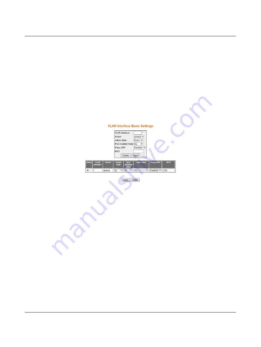
Figure 3-5
“VLAN Interface Basic Settings” page
The “VLAN Interface Basic Settings” page configures:
From the second entry panel which begins with the Select column.
Select:
Select the VLAN Interface for which configuration needs to be modified or deleted.
In this case it will be VLAN interface #1.
VLAN Interface:
Enter
1
.
Switch:
default.
Admin State:
Select “Up” from the drop-down menu.
IPv4 Enabled State:
Select the status of IPv4 on the interface. The default option is
Up
.
Select “Up” from the drop-down menu.
Operating State:
Select “Up” from the drop-down menu.
Proxy ARP:
Select the Proxy ARP admin status for the interface. The default option is
Disabled
.
MTU:
Enter
1500
in the “MTU” field.
Click the “Apply” button.