background image

1

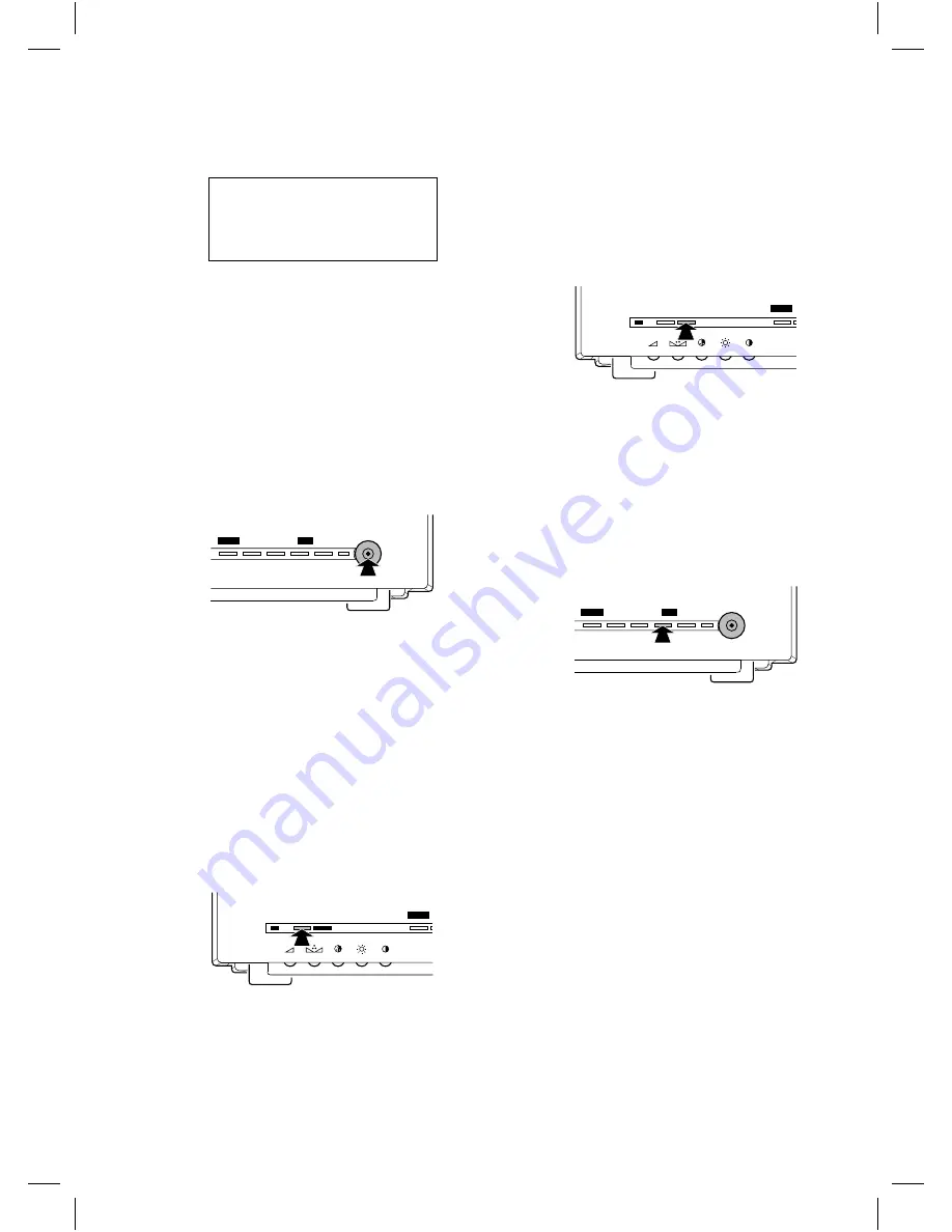
Power on

The monitor switches ON.

The following text appears on the monitor screen:

PHILIPS

OBSERVATION SYSTEM

VERSION x.x

SYSTEM CHECK

(x.x = version number)

After approximately 30 seconds or when a button is
pressed the camera image appears on the monitor screen.

Remark:

At the first installation or when one or more cameras

or accessories were added or removed from the system, the text
CONFIGURATION CHANGED will appear on the monitor
screen. In this way the monitor indicates that it has stored the
new system configuration.

2

Power off

The monitor switches OFF (system mode indication
LED is off).

Power save/active

1

Power active

Image and sound of the monitor are switched on (power
indication LED is green)

2

Power save

Image and sound of the monitor are switched off. The
camera continues to transmit images and sound to the
VCR, slave and aux. output. The alarm functions also
remain active.

In power save mode you can select between two
functions (selection is menu controlled):

non-silent function (system mode indication LED is red)

silent function (system mode indication LED is amber)

Talk function

Press

H

to speak through the intercom (optional).

Release the button to allow your visitor to speak to you.

Doorbell function:

If the doorbell button on the intercom box is pressed a
buzzer sounds and the symbol

u

is visible at the upper

left-hand side of the monitor screen. The monitor
switches to the camera input the intercom box is
designated to.

Remark:

The talk button and doorbell function are only

functional in combination with an intercom box (optional).

Action function

Press

I

, for instance to open a door. As long as

I

is pressed, a buzzer sounds and the symbol

U

is visible at the upper left-hand side of the monitor
screen. If the system consists of more cameras, the action
is done in the action box designated to the selected
camera input.

Remark:

The action button is only functional in combination

with an Alarm/Action box (optional).

Auto sequence on/off

off
The monitor displays the image (and sound) of one of
the connected cameras. The selected camera input
number is visible at the upper left-hand corner of the
monitor screen. Press

K

or

L

to select the

previous or next camera input.

on
The monitor switches slowly between the pictures (image
+ sound) of the connected cameras. The camera line
number and the symbol

V

are visible at the upper

left-hand corner of the screen.

Remark:

The

auto

button is only functional when:

camera mode is selected

the observation system is enlarged to at least two cameras

no menu is displayed

CL 66610005_012.AI

menu

_

+

next

auto

view

CL 66610005_015.AI

talk action

menu

CL 66610005_016.AI

talk action

menu

CL 66610005_017.AI

menu

_

+

next

auto

view

g

6

Summary of Contents for VSS7370/00T

Page 1: ...operate observation and security system Operation and programming of the system is performed through On Screen Display OSD menus With these menus you can adapt the system to your own convenience If you follow the installation and operation instructions as described in the following sections you will quickly learn how to adjust and operate your observation system The following items are included in...

Page 2: ... Menu off This button selects the next camera input video image sound Menu on This button increases or changes the value of a selected menu item 7 Auto next N There are two possibilities Menu off This button switches the auto sequence function on off Remark Auto sequence is only functional when you have installed more than one camera Menu on This button selects the next menu item 8 View J Press th...

Page 3: ...e scanned again Therefore always switch off the system when a camera or accessory is added or removed Only operating the power save button is not sufficient Camera To ease the installation of the camera take it and the system monitor to the area you want to observe With the monitor on site you can check whether the camera covers the required area For the installation of the camera you should consu...

Page 4: ...n on the intercom box is pressed a buzzer sounds and the symbol u is visible at the upper left hand side of the monitor screen The monitor switches to the camera input the intercom box is designated to Remark The talk button and doorbell function are only functional in combination with an intercom box optional Action function Press I for instance to open a door As long as I is pressed a buzzer sou...

Page 5: ...s are lost Use the AUTO INSTALL function see Installation Menu to scan the system The system monitor will register the camera configuration again How do the menus work With the On Screen Display menus you can adjust various system control functions The following menus can be selected The menu control buttons The menus are operated with the following control buttons 1 M Switches the main menu on of...

Page 6: ...NT is highlighted Press K or L to deactivate OFF or activate ON the silent function 4 Alarm history list HISTORY When you select HISTORY a list with the date time kind of alarm and the camera input number of the last 9 alarm events is displayed Select HISTORY from the Main Menu Press N until the symbol Y next to HISTORY is highlighted Press K or L r The history list appears Press M when you want t...

Page 7: ...ll Menu Press N until the symbol Y next to AUTO INSTALL is highlighted Press K or L to start the installation procedure r The text SYSTEM CHECK appears on the monitor screen After approximately 20 seconds the following texts can appear on the monitor screen AUTO INSTALL COMPLETED r The system is installed correctly After approximately 30 seconds or when a button is pressed the Install Menu returns...

Page 8: ...n is pressed the message will disappear from the monitor screen Remark Although the cameras will work none of the accessories in any line will be functioning No valid camera input selection The camera number of an intercom box or Alarm Action box cannot be set to a camera input to which no camera is connected If the system monitor detects an invalid camera input selection it shows the following me...

Page 9: ...tector PIR Remark One camera line can contain up to two intercom boxes and two Alarm Action boxes with or without PIR Interface box By means of the interface box it is possible to add or extract standard video and audio signals from the system cable e g to connect third party cameras or a cash register interface Mains power adaptor If the camera cable is more than 200m 600ft this adaptor must be u...

Page 10: ...utput 1 system interface Microphone electret Frequence range 300 3kHz Alarm output 4 pole screwblock N O N C contact system ground Contact rating 24VDC 2A VCR Video input BNC 1Vpp input impedance 75Ohm Audio input Cinch 0 5Vpp input impedance 10kOhm Video output BNC 1Vpp output impedance 75Ohm Audio output Cinch 0 5Vpp output impedance 1kOhm AUX Video output BNC 1Vpp output impedance 75Ohm Audio o...

Reviews: