


3.4 Slide the pieces together
1
To complete the installation, simply slide
the mount with your LCD attached into
the wall piece. The plastic tab at the top of
wall piece should click indicating that the
mount is secure.
2
To remove the mount, push in on the
plastic tab and then slide the mount up.
3
For additional security and stability, tighten
the set screw located on the base of the
arm piece using the 3 mm allen key (I)
supplied in the hardware kit.
5
5
B
Warning
Insert the safety screw at the bottom
of the mount to avoid having the
display accidentally knocked off the
mount.
4
Use the cable management hooks (see
illustration) to keep the power cord and
other cables for your display in order while
adjusting the mount.
6
7LOW$GMXVWPHQW.QRE
-RLQW
3ODVWLF7DE
6HW6FUHZ
&DEOH
0DQDJHPHQW
+RRNV
6
5
To change the tilt angle, hold the display
with one hand and loosen the tilt
adjustment knob. Move the display to the
desired position and re-tighten the knob.
Other adjustments can be made by simply
moving the mount into the desired position.
6
If you find that a joint is too difficult to move
or has become too loose, you can adjust the
tightness of that joint using the 4 mm allen
key (J) supplied in the hardware kit.
4 Guarantee and service
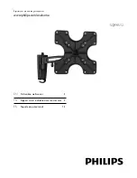
Please contact Philips directly if you have any
questions in the installation process of the wall
mount. Call 1-919-573-7854.
Limited Two-Year Warranty
Philips warrants that this product shall be free
from defects in material, workmanship and
assembly, under normal use, in accordance with
the specications and warnings, for two years
from the date of your purchase of this product.
This warranty extends only to the original
purchaser of the product, and is not transferable.
To exercise your rights under this warranty, you
must provide proof of purchase in the form of
an original sales receipt that shows the product
name and the date of purchase. For customer
support or to obtain warranty service, please
call 919-573-7854. THERE ARE NO OTHER
EXPRESS OR IMPLIED WARRANTIES. Philips’
liability is limited to repair or, at its sole option,
replacement of the product. Incidental, special
and consequential damages are disclaimed where
permitted by law. This warranty gives you specic
legal rights. You may also have other rights that
vary from state to state.
Register your product and get support at
www.philips.com/welcome