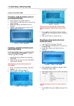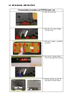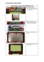
5 Remove two screws
6 Remove four screws and take
out cover hinge .
7 Remove ten screws , get PCBA
key board.
8 Remove two screws and take
out the 12pin cable from the hole.
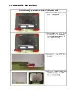
9 After 8 procedure, we get TFT
assembly and middle cabinet.
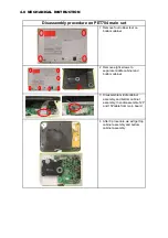
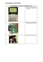
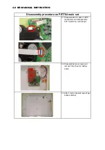
Disassembly procedure on PET704 main set
4.0 MECHANICAL INSTRUCTION
Summary of Contents for PET704
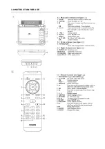
Page 7: ...3 0 INSTRUCTION FOR USE ...
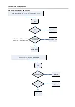
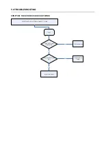
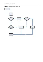
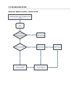
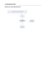
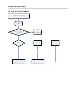
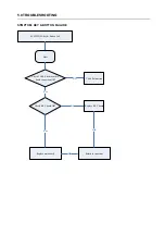
Page 19: ...5 0 TROUBLESHOOTING SYMPTOM NO SOUND FROM HEADPHONE ...
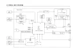
Page 22: ...6 0 OVERALL BLOCK DIAGRAM ...
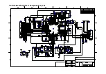
Page 23: ...7 0 Electrical Diagram Component Layout ...
Page 24: ...7 0 Electrical Diagram Component Layout ...
Page 25: ...7 0 Electrical Diagram Component Layout ...
Page 26: ...7 0 Electrical Diagram Component Layout MAIN PCB TOP LAYER ASSEMBLY ...
Page 27: ...7 0 Electrical Diagram Component Layout MAIN PCB BOTTOM LAYER ASSEMBLY ...
Page 28: ...7 0 Electrical Diagram Component Layout MAIN PCB TOP LAYER SILKSCREEN ...
Page 29: ...7 0 Electrical Diagram Component Layout MAIN PCB BOTTOM LAYER SILKSCREEN ...
Page 30: ...7 0 Electrical Diagram Component Layout CHARGE PCB TOP LAYER ASSEMBLY ...
Page 31: ...7 0 Electrical Diagram Component Layout CHARGE PCB BOTTOM LAYER ASSEMBLY ...
Page 32: ...7 0 Electrical Diagram Component Layout CHARGE PCB TOP LAYER SILKSCREEN ...
Page 33: ...7 0 Electrical Diagram Component Layout CHARGE PCB BOTTOM LAYER SILKSCREEN ...
Page 34: ...7 0 Electrical Diagram Component Layout ...


