1 - 4
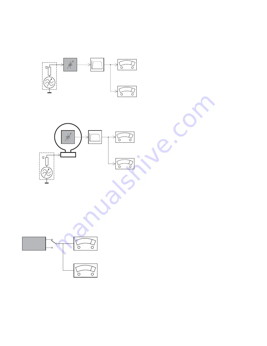
LEVEL METER
e.g. Sennheiser UPM550
with FF-filter
S/N and distortion meter
e.g. Sound Technology ST1700B
L
R
DUT
CD
Use Audio Signal Disc
(replaces test disc 3)
SBC429 4822 397 30184
Bandpass
250Hz-15kHz
e.g. 7122 707 48001
LF Voltmeter
e.g. PM2534
DUT
S/N and distortion meter
e.g. Sound Technology ST1700B
Frame aerial
e.g. 7122 707 89001
Tuner AM (MW,LW)
To avoid atmospheric interference all AM-measurements have to be carried out in a Faraday´s cage.
Use a bandpass filter (or at least a high pass filter with 250Hz) to eliminate hum (50Hz, 100Hz).
RF Generator
e.g. PM5326
Ri=50
Bandpass
250Hz-15kHz
e.g. 7122 707 48001
LF Voltmeter
e.g. PM2534
DUT
RF Generator
e.g. PM5326
S/N and distortion meter
e.g. Sound Technology ST1700B
Use a bandpass filter to eliminate hum (50Hz, 100Hz) and disturbance from the pilottone (19kHz, 38kHz).
Ri=50
Tuner FM
MEASUREMENT SETUP
Summary of Contents for MCM765
Page 9: ...SET BLOCK WIRING DIAGRAM 3 1 3 1 ...
Page 10: ...CIRCUIT DIAGRAM MAIN BOARD AUDIO POWER AMP SECTION only for 55 77 4 1 4 1 ...
Page 11: ...CIRCUIT DIAGRAM MAIN BOARD AUDIO POWER AMP SECTION only for 85 4 2 4 2 ...
Page 12: ...4 3 4 3 CIRCUIT DIAGRAM MAIN BOARD MCU POWER SUPPLY SECTION ...
Page 13: ...4 4 4 4 LAYOUT DIAGRAM MAIN BOARD TOP VIEW ...
Page 14: ...4 5 4 5 LAYOUT DIAGRAM MAIN BOARD BOTTOM VIEW ...
Page 15: ...4 6 4 6 LAYOUT DIAGRAM HEADPHONE BOARD ...
Page 16: ...5 1 5 1 CIRCUIT DIAGRAM FRONT BOARD ...
Page 17: ...5 2 5 2 LAYOUT DIAGRAM FRONT BOARD TOP VIEW ...
Page 18: ...5 3 5 3 LAYOUT DIAGRAM FRONT BOARD BOTTOM VIEW ...
Page 19: ...6 1 6 1 LAYOUT DIAGRAM TOP KEY BOARD TOP VIEW ...
Page 20: ...6 2 6 2 LAYOUT DIAGRAM TOP KEY BOARD BOTTOM VIEW ...
Page 21: ...CIRCUIT DIAGARM CD BOARD 7 1 7 1 ...
Page 22: ...LAYOUT DIAGARM CD BOARD TOP VIEW 7 2 7 2 ...
Page 23: ...LAYOUT DIAGARM CD BOARD BOTTOM VIEW 7 3 7 3 ...
Page 24: ...8 1 8 1 CIRCUIT DIAGRAM CASSETTE BOARD ...
Page 25: ...8 2 8 2 2 1 3 4 LAYOUT DIAGRAM CASSETTE BOARD COMPONENT SIDE COPPER SIDE ...