background image

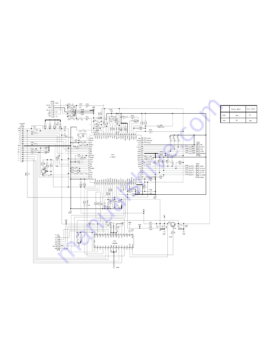
CIRCUIT DIAGARM - CD BOARD

7 - 1

7 - 1

Summary of Contents for MCM765

Page 1: ...the prior permission of Philips Published by SL 0842 Service Audio Printed in The Netherlands Subject to modification Micro System Version 1 1 CLASS 1 LASER PRODUCT 3141 785 32811 TABLE OF CONTENTS Page PCBs Location 1 2 Specifications 1 3 Measurement Setup 1 4 Service Aids Safety Instruction etc 1 5 to 1 7 Service Test Mode 2 Set Block Diagram Set Wiring Diagram 3 Main Board HP Board 4 Front Boar...

Page 2: ...es Voltage Selector ECO Power Standby LCD Display Off USB Direct Type Versions Features in used 55 VERSION VARIATIONS Type Versions Board in used MCM765 Service policy MAIN BOARD KEY TOP KEY BOARD FRONT BOARD CASSETTE BOARD TIPS C Component Lever Repair M Module Lever Repair Used 05 12 55 85 77 Feature diffrence C CD BOARD C C C TUNER MODULE M x x C SWITCHING SUPPLY MODULE M AC CORE BOARD C C C C ...

Page 3: ...es maximum 500 TUNER FM wave range 87 5 108 MHz Sensitivity at 75 mono 26 dB signal to noise ratio 2 8 µV stereo 46 dB signal to noise ratio 61 4 µV Total harmonic distortion d 5 Frequency response 63 12500 Hz 3 dB Signal to noise ratio t 50 dBA TAPE DECK Frequency response Normal tape type I 80 12500 Hz 8 dB Signal to noise ratio Normal tape type I 50 dBA Wow and flutter d 0 4 DIN SPEAKERS System...

Page 4: ...7122 707 89001 Tuner AM MW LW To avoid atmospheric interference all AM measurements have to be carried out in a Faraday s cage Use a bandpass filter or at least a high pass filter with 250Hz to eliminate hum 50Hz 100Hz RF Generator e g PM5326 Ri 50 Bandpass 250Hz 15kHz e g 7122 707 48001 LF Voltmeter e g PM2534 DUT RF Generator e g PM5326 S N and distortion meter e g Sound Technology ST1700B Use a...

Page 5: ...ng make sure that you are connected with the same potential as the mass of the set via a wrist wrap with resistance Keep components and tools also at this potential ESD CLASS 1 LASER PRODUCT GB Safety regulations require that the set be restored to its original condition and that parts which are identical with those specified be used Safety components are marked by the symbol Lead free ...

Page 6: ...T OK check playability N Y playability ok check playability check playability return set Customer complaint CD related problem fast lens cleaning 1 2 3 For flap loaders access to CD drive possible cleaning method 4 is recommended INSTRUCTIONS ON CD PLAYABILITY 1 6 Exchange CDM 1 4 For description see following pages ...

Page 7: ...viously caused by a scratched dirty or copy protected CD In case problems remain the customer is requested to contact the workshop directly The lens cleaning method 3 should be mentioned in the addendum sheet The final wording in national language as well as the printing is under responsibility of the Regional Service Organizations 4 LIQUID LENS CLEANING Because the material of the lens is synthet...

Page 8: ...wer ON Mode Hold PLAY key for 5s LCD will show the data code and version number 4 USB Version Check 1 In Power ON USB Mode Hold STOP and SOURCE key for 5s LCD will show the USB chip version number MM SS M main ver S sub ver 5 USB Version Update 1 In Power ON CD Mode Hold STOP and FB key for 5s LCD will sh ow the UPDATE 2 Plug in USB drive will show LOADING 3 Wait until the screen show LOAD OK and ...

Page 9: ...SET BLOCK WIRING DIAGRAM 3 1 3 1 ...

Page 10: ...CIRCUIT DIAGRAM MAIN BOARD AUDIO POWER AMP SECTION only for 55 77 4 1 4 1 ...

Page 11: ...CIRCUIT DIAGRAM MAIN BOARD AUDIO POWER AMP SECTION only for 85 4 2 4 2 ...

Page 12: ...4 3 4 3 CIRCUIT DIAGRAM MAIN BOARD MCU POWER SUPPLY SECTION ...

Page 13: ...4 4 4 4 LAYOUT DIAGRAM MAIN BOARD TOP VIEW ...

Page 14: ...4 5 4 5 LAYOUT DIAGRAM MAIN BOARD BOTTOM VIEW ...

Page 15: ...4 6 4 6 LAYOUT DIAGRAM HEADPHONE BOARD ...

Page 16: ...5 1 5 1 CIRCUIT DIAGRAM FRONT BOARD ...

Page 17: ...5 2 5 2 LAYOUT DIAGRAM FRONT BOARD TOP VIEW ...

Page 18: ...5 3 5 3 LAYOUT DIAGRAM FRONT BOARD BOTTOM VIEW ...

Page 19: ...6 1 6 1 LAYOUT DIAGRAM TOP KEY BOARD TOP VIEW ...

Page 20: ...6 2 6 2 LAYOUT DIAGRAM TOP KEY BOARD BOTTOM VIEW ...

Page 21: ...CIRCUIT DIAGARM CD BOARD 7 1 7 1 ...

Page 22: ...LAYOUT DIAGARM CD BOARD TOP VIEW 7 2 7 2 ...

Page 23: ...LAYOUT DIAGARM CD BOARD BOTTOM VIEW 7 3 7 3 ...

Page 24: ...8 1 8 1 CIRCUIT DIAGRAM CASSETTE BOARD ...

Page 25: ...8 2 8 2 2 1 3 4 LAYOUT DIAGRAM CASSETTE BOARD COMPONENT SIDE COPPER SIDE ...

Page 26: ...eft hand screw right hand screw max output level left right WOW FLUTTER ADJUST AZIMUTH 3150Hz 2 0 4 DIN to 1 2 or LEFT RIGHT Inject 3mV signals 100Hz 250Hz 1kHz 10kHz 12 5kHz 1 2 or LEFT RIGHT Inject 1kHz 8 85mV 3 4 or via 3 4 or via 1 2 or LEFT RIGHT RECORD RECORD PLAY PLAY mV meter THD meter check check limits see fig 2 3 RECORDED CASSETTE RECORDED CASSETTE figure 1 f Hz level dB 8dB 6dB 12 5k 4...

Page 27: ...SET MECHANICAL EXPLODED VIEW 9 1 9 1 18 VKSW 33 10 34 31 30 35 24 25 20 19 21 27 22 DAMP 32 23 TRAF 3 32 26 17 1 14 12 CADS SWS 13 38 28 29 CDS2 CDT DAMP 15 CDS1 CDM 16 ...

Page 28: ...0001409 CD DOOR GEAR HOLDER 12 996510000402 BRACKET PUSH LOCK 13 994000001412 PUSH LOCK FOR CASSETTE DOOR 14 994000004801 BRACKET CASSETTE DOOR 15 996510002333 TOP CABINET 16 996510002334 LEFT CABINET 16 996510002334 LEFT CABINET 17 996510002335 RIGHT CABINET 18 996510002337 VOLUME KNOB Note Only these parts mentioned in the list are 19 996510017001 POWER KEY normal service parts 20 996510002342 P...

Page 29: ...01 994000003206 TRANSISTOR 8550D C1001 996510018688 AL E CAP 6800UF 35V Q1602 996510016572 TRANSISTOR KTC8050S SOT 23 C1002 996510018688 AL E CAP 6800UF 35V Q2205 994000003206 TRANSISTOR 8550D C1002 996510018688 AL E CAP 6800UF 35V Q2205 994000003206 TRANSISTOR 8550D C1119 996510012837 CBB CAP HMFS 5 0 68UF 63V Q2208 994000003206 TRANSISTOR 8550D C1120 996510012837 CBB CAP HMFS 5 0 68UF 63V Q2210 ...

Page 30: ...P E PROGRAMMED U3201 996510010763 IC AT24C02BN SH T U701 994000003214 VFD DRIVER IC PT6315 VFD701 996510016575 DISPLAY VFD25 1236N X702 996510016576 X TAL 12MHZ 20PF 20PPM Y3101 996510003839 X TAL 32 768KHZ 12 5PF Y3102 996510016577 X TAL 8MHZ 20PF 20PPM ZD1101 996510004557 DIODE 5V6 1 2W TCLLZ5V6 LL34 ZD2202 996510011335 ZENER DIODE 10V 1 2W ZD2202 996510011335 ZENER DIODE 10V 1 2W ZD2203 9940000...

Page 31: ...32810 Initial Service Manual released 1 1 Manual 3141 785 32811 In this version on Page 9 2 Mechanical Accessories Parts List updated REM 996510019921 REMOTE CONTROL 85 WAS 996510002352 REM 996510019920 REMOTE CONTROL 55 77 WAS 996510002352 ...

Reviews: