Technical Specification and Connection Facilities
1-4
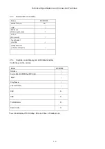
2.1.5.
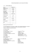
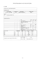
ACCESSORIES (tbc)
Model
MCM7000
Stroke Version
12
e
p
o
r
u
E
n
o
i
g
e
R
Power Cord
1.8M
AV cable
1.5M
Audio cable
(3.5mm audio)
0.5M
Tuner Antenna
1.5M 75ohm
Speaker cable
3M
USB cable
NA
Remote Control
44keys
Battery
AAAx2
Quickly guide
1
IFU
1
3.Mechanical General Information
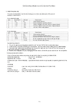
The product appearances and functions are defined in their respective MUS.Product management
approves the MUS and it is a leading document where product appearance is applicable.
Please refer to Sh560 for mechanical information.
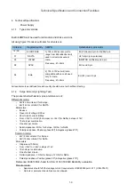
3.1.Safety Standards
Where applicable:
For /12 (EU), /05 (UK), /51 (Russia)
EN/IEC 60065 7
th
Edition
5
6
0
0
6
L
U
)
a
d
a
n
a
C
,
S
U
(
7
3
/
r
o
F
7
5
6
0
0
6
C
E
I
)
li
z
a
r
B
(
8
7
/
,
)
M
A
T
A
L
(
5
5
/
r
o
F
th
Edition
For /98 (AP), /69 (Singapore), /75 (Australia)
IEC 60065 7
th
Edition
7
5
6
0
0
6
C
E
I
(
8
9
8
8
B
G
)
a
n
i
h
C
(
3
9
/
r
o
F
th
Edition)
6
5
6
0
0
6
K
)
a
e
r
o
K
(
1
6
/
r
o
F
th
Edition
7
5
6
0
0
6
C
E
I
(
8
0
4
4
1
S
N
C
)
n
a
w
i
a
T
(
6
9
/
r
o
F
th
Edition)
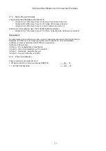
3.2.EMC Requirements
Where applicable:
For /12 (EU), /05 (UK), /51 (Russia)
EN55013: 2001, EN55020: 2002
5
1
C
C
F
)
a
d
a
n
a
C
,
S
U
(
7
3
/
r
o
F
3
1
R
P
S
I
C
)
li
z
a
r
B
(
8
7
/
,
)
M
A
T
A
L
(
5
5
/
r
o
F
For /98 (AP), /69 (Singapore), /75 (Australia)
CISPR13
0
2
/
3
1
R
P
S
I
C
)
a
e
r
o
K
(
1
6
/
r
o
F
)
3
1
R
P
S
I
C
(
7
3
8
3
1
B
G
)
a
n
i
h
C
(
3
9
/
r
o
F
)
3
1
R
P
S
I
C
(
9
3
4
3
1
S
N
C
)
n
a
w
i
a
T
(
6
9
/
r
o
F
Summary of Contents for MCM7000/12
Page 30: ...AMP BOARD Layout Diagram 12 2 12 2 ...
Page 32: ...Display Board Layout Diagram 12 4 12 4 ...
Page 35: ...Key Board Layout Diagram 12 7 12 7 ...
Page 38: ...T5AH 250V Power Board Layout Diagram 12 10 12 10 ...
Page 42: ...Decoder Board Layout Diagram 12 14 12 14 ...
Page 44: ...Revision List Revision List Version 1 0 Initial Release 14 1 ...

