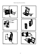
Direction of Use
7-3
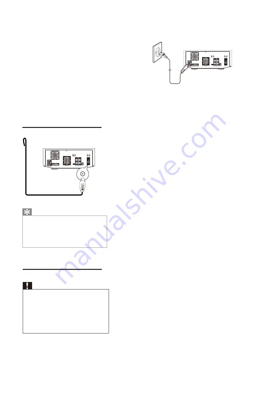
Connect power
Caution
Risk of product damage! Ensure that the
power supply voltage corresponds to the
voltage printed on the back or the underside
of the unit.
Risk of electric shock! When you unplug the
AC power cord, always pull the plug from the
socket. Never pull the power cord.
Before you connect the AC power cord,
ensure that you have completed all other
connections.
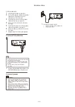
1
Connect the power cord to:
the
AC~ socket on the main unit.
the power outlet.
R
R
AU X IN
LINE OU T
L
L
DEMO
ANTENN A
FM
For the speaker side:
1
Unscrew the speaker connectors.
2
For the left speaker, identify the speaker
cable that is connected to the left
connectors on the main unit.
3
Insert fully the red end of the speaker
cable into the red (+) connector.
4
Screw the red (+) connector to secure
the cable.
5
Insert fully the silver end of the speaker
cable into the black (-) connector.
6
Screw the black (-) connector to secure
the cable.
7
Repeat steps 2-6 for the right speaker.
Connect FM antenna
Tip
For optimal reception, fully extend and adjust
the position of the antenna.
For better FM stereo reception, connect an
outdoor FM antenna to the FM ANTENNA
socket.
The unit does not support MW radio
reception.
1
Connect the supplied FM antenna to the
FM ANTENNAsocket on the main unit.
R
R
AU X IN
LINE OU T
L
L
DEMO
ANTENNA
FM
FM
Summary of Contents for MCM7000/12
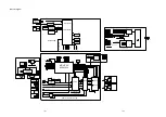
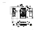
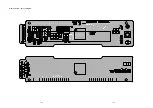
Page 30: ...AMP BOARD Layout Diagram 12 2 12 2 ...
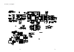
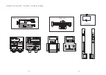
Page 32: ...Display Board Layout Diagram 12 4 12 4 ...
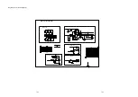
Page 35: ...Key Board Layout Diagram 12 7 12 7 ...
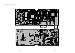
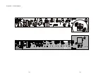
Page 38: ...T5AH 250V Power Board Layout Diagram 12 10 12 10 ...
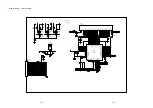
Page 42: ...Decoder Board Layout Diagram 12 14 12 14 ...
Page 44: ...Revision List Revision List Version 1 0 Initial Release 14 1 ...

