background image

1-3

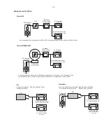
LF Generator 

e.g. PM5110

Recorder

Use Universal Test Cassette 

CrO2

SBC419  4822 397 30069

LEVEL METER

e.g. Sennheiser UPM550

with FF-filter

with FF-filter

S/N and distortion met

e.g. Sound Technology ST170

L

R

DUT

or Universal Test Cassette 

Fe

SBC420  4822 397 30071

LEVEL METER

e.g. Sennheiser UPM550

S/N and distortion meter

e.g. Sound Technology ST1700B

L

R

DUT

CD

Use Audio Signal Disc
(replaces test disc 3)

SBC429  4822 397 30184

Bandpass

250Hz-15kHz

e.g. 7122 707 48001

LF Voltmeter

 e.g. PM2534

DUT

S/N and distortion meter

 e.g. Sound Technology ST1700B

Frame aerial

e.g. 7122 707 89001

Tuner AM (MW,LW)

To avoid atmospheric interference all AM-measurements have to be carried out in a Faraday´s cage.
Use a bandpass filter (or at least a high pass filter with 250Hz) to eliminate hum (50Hz, 100Hz).

RF Generator 

e.g. PM5326

0

5

=i

R

Bandpass

250Hz-15kHz

e.g. 7122 707 48001

LF Voltmeter

 e.g. PM2534

DUT

RF Generator 

e.g. PM5326

S/N and distortion meter

 e.g. Sound Technology ST1700B

Use a bandpass filter to eliminate hum (50Hz, 100Hz) and disturbance from the pilottone (19kHz, 38kHz).

0

5

=i

R

Tuner FM

Measurement Setup

Summary of Contents for MCD110

Page 1: ...e Version Check Upgrade 2 1 Malfuction Check Chart 2 2 Disassembly Diagram 3 1 Block Diagram 4 1 Wiring Diagram 4 2 USB Board 5 Circuit diagram 5 1 Layout diagram 5 1 LED Display Board 6 Circuit diagram 6 1 Layout diagram 6 2 Power Board 7 Circuit diagram 7 1 Layout diagram 7 2 Exploded View 9 1 Service Parts List 10 1 Factory Parts List 11 1 to 11 2 MCD110 Decoder Board 8 Circuit Diagram 8 1 to 8...

Page 2: ... BOARD POWER BOARD USB BOARD DECODER BOARD TIPS C Component Lever Repair M Module Lever Repair Used 55 55 58 58 61 61 79 79 93 93 94 94 96 96 98 98 37 37 12 12 05 05 Feature diffrence RDS TDS VOLTAGE SELECTOR ECO STANDBY DARK C C M M Type Versions MCD110 Decoder Board Power Board LED Display Board USB Board 1 1 ...

Page 3: ... Total Harmonic Distortion 1 6LJQDO WR 1RLVH 5DWLRQ G SPEAKERS Speaker Impedance NA e Speaker Driver base NA Speaker Driver tweeter NA Frequency Response NA GENERAL INFORMATION Total Output power NA AC Power 220V 50Hz Operation Power Consumption 6W Standby Power Consumption NA Eco Standby Power Consumption 0 5W Headphone Output NA USB Direct Version 2 0 Dimensions Main unit w x h x d 220x90x240mm ...

Page 4: ...Hz e g 7122 707 48001 LF Voltmeter e g PM2534 DUT S N and distortion meter e g Sound Technology ST1700B Frame aerial e g 7122 707 89001 Tuner AM MW LW To avoid atmospheric interference all AM measurements have to be carried out in a Faraday s cage Use a bandpass filter or at least a high pass filter with 250Hz to eliminate hum 50Hz 100Hz RF Generator e g PM5326 0 5 i R Bandpass 250Hz 15kHz e g 712...

Page 5: ...rist wrap with resistance Keep components and tools also at this potential ESD CLASS 1 LASER PRODUCT GB Safety regulations require that the set be restored to its original condition and that parts which are identical with those specified be used Safety components are marked by the symbol Philips CE is producing lead free sets from 1 1 2005 onwards Regardless of special logo not always indicated on...

Page 6: ...soon as possible During handing sealed ES parts reduce the movement of the body clothes rubbing and moving on the rug can generate static charge to damage the ES parts Maintenance Attention Common Soldering Rules Use only grounded low voltage soldering iron and proper size and shape which can sustain the temperature of soldering horn to range from 350 to 390 Use rosin flu which is demanded by RMA ...

Page 7: ...Cut the unwand lead T D D No sound or sound distorted when playing please check the DVD part N Before operating read these notes as following to prevent the static charges damageing the laser head when reading the laser led Lay an electric rug on the working table and the replaced parts are packed in black package The electric rug is grounding by put on the electric base Then put your hand on the ...

Page 8: ...RU FXVWRPHU 6 7 2 FKHFN SOD DELOLW 1 SOD DELOLW RN FKHFN SOD DELOLW FKHFN SOD DELOLW UHWXUQ VHW XVWRPHU FRPSODLQW UHODWHG SUREOHP IDVW OHQV FOHDQLQJ RU IODS ORDGHUV DFFHVV WR GULYH SRVVLEOH FOHDQLQJ PHWKRG LV UHFRPPHQGHG FKDQJH 0 RU GHVFULSWLRQ VHH IROORZLQJ SDJHV QVWUXFWLRQ 2Q 3OD DELOLW ...

Page 9: ...UREOHPV UHPDLQ WKH FXVWRPHU LV UHTXHVWHG WR FRQWDFW WKH ZRUNVKRS GLUHFWO 7KH OHQV FOHDQLQJ PHWKRG VKRXOG EH PHQWLRQHG LQ WKH DGGHQGXP VKHHW 7KH ILQDO ZRUGLQJ LQ QDWLRQDO ODQJXDJH DV ZHOO DV WKH SULQWLQJ LV XQGHU UHVSRQVLELOLW RI WKH 5HJLRQDO 6HUYLFH 2UJDQL DWLRQV 48 16 1 1 HFDXVH WKH PDWHULDO RI WKH OHQV LV V QWKHWLF DQG FRDWHG ZLWK D VSHFLDO DQWL UHIOHFWLYLW OD HU FOHDQLQJ PXVW EH GRQH ZLWK D QRQ...

Page 10: ...state or STOP status at the next press the SYSTEM MENU on remote control TV Screen Display Upgrade file detected Upgrade Press Play to start Upgrade file detected Do not power off Upgrading Press Play on the main set 1 Download the software from Philips support website 2 Load the CD Disc or USB device with software Software upgrade procedure starts automatically TV Screen Display http www philips ...

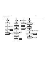
Page 11: ...work Plug in the power cord Reset the Time Clock Replace a new Power Board Check the USB or other devices are connected Check if the USB or other devices are incompatible Check the data wire which connected the Main Board if has provided voltage Check if has voltage supply to the USB Board Check if the CPU IC has provided voltage Check if the VFD Board has provided voltage No Replace a new one No ...

Page 12: ...o remove the Power Board E Remove Decoder Board E1 Loose 2pcs screws 3 x 10 FA of the back side E2 Loose 2pcs screws 3 x 8 BA of the decoder board D Loose 4pcs screws 3 x 10 PWA to remove DVD Loader Driver F Loose 2pcs screws 3 x 8 FT to remove the Front Cabinet G Loose 1pc screw 3 x 8 BA to remove the Headphone Board A Open the DVD Door and loose 2 clipps to remove the door H Loose 6pcs screws 2 ...

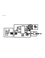
Page 13: ...888S A5V YUV RGB CVBS USB I2C AISHANG Pick Up DVD Loader 5V 5V AC INPUT MUTE1 MUTE OP CL MTL1389DE LESL Main chipset AUDIO L ROUT M3 3V M1 8V A5V RESET AISHANG DVD LOADER POWER BOARD POW352 MPEG BOARD 1 2 1 2 3 1 2 GND 1 2 3 GND 1 2 3 4 5 6 7 7P GND A5V IR DATA CLK STB ECO POWER 1 2 3 4 5 6 7 7P GND IR DATA CLK STB ECO POWER 1 2 3 4 5 6 6P 1 2 3 4 5 6 6P 1 2 3 4 5 5P 1 2 3 4 5 5P OP OP CL CL GND G...

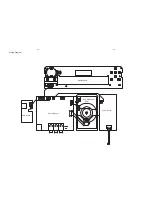
Page 14: ...4 2 4 2 Wiring Diagram Display Board DVD Mechanism Driver Power Board Decoder Board USB Board ...

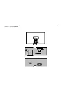
Page 15: ...5 1 5 1 Small Board Layout Circuit Diagram vbus 1 D 2 D 3 GND 4 Shield 5 GND 6 J201 USB GND 2 D D VBUS 1 2 3 4 CN201 4PIN 2 0 ...

Page 16: ...04 100uF OSC 1 DI O 2 CLK 3 STB 4 KEY1 5 KEY2 6 VDD 7 Seg1 Ks1 8 Seg2 Ks2 9 Seg3 Ks3 10 Seg4 Ks4 11 Seg5 Ks5 12 Seg6 Ks6 13 Seg7 Ks7 14 Seg8 Ks8 15 Seg9 Ks9 16 Seg10 Ks10 17 Seg12 Gnd7 18 Seg13 Gnd6 19 Seg14 Gnd5 20 VDD 21 GND 22 Grid4 23 Grid3 24 GND 25 Grid2 26 Grid1 27 GND 28 U101 TM1628 C1 1 C2 2 C3 3 C4 4 C5 5 C6 6 DF 7 G 8 F 9 E 10 D 11 C 12 B 13 A 14 LED101 LED1 ULX 3661CY C101 104 R101 56K...

Page 17: ...6 2 6 2 LED Display Board Layout Diagram ...

Page 18: ...IC2 2 1 3 1 2 3 4 5 6 7 8 R16 VR1 YT1604 IC1 07561 C3 CON1 2P 104 280V 1MR 1206 10uF 450V 10uF 450V 1N4007 C2 150K 1206 R3 150K 1206 103 1KV R4 C5 FR107 D5 FR107 R6 2 7KR 0805 C10 1000uF 10V 4 7K 0805 R11 1000uF 10V C11 560R 1206 R15 82K 0805 R10 82K 0805 R9 R6 2 7KR 0805 D6 1R 1W R1 10R 1206 R6 C1 D3 1N4007 D1 22uF 50V F1 T2A 250V RT1 1 2 10D9 C6 2A681 50V C4 104 0805 C12 1N4007 D2 1N4007 D4 L1 ...

Page 19: ...Power Board Layout Diagram 7 3 7 3 ...

Page 20: ... 89L Defau lt TXD1 for 89L Defau lt RXD2 TXD2 VSTB TRCLOSE MUTE MS_CLK SD_CLK MS_BS SD_CMD MS_D0 SD_D0 TROUT LIMIT ASP DIF TRIN LED_I O VSYNC HSYNC Audio_SUB Audio_RSCH Audio_RCH Audio_LCH Audio_LSCH Audio_CENT VSTB TRCLOSE MUTE MS_CLK SD_CLK MS_BS SD_CMD MS_D0 SD_D0 TROUT LIMIT ASP DIF TRIN FS1 RGB_SW FS0 Audio_SUB Audio_RSCH Audio_RCH Audio_LCH Audio_LSCH Audio_CENT MIC card VGA VGA scart card c...

Page 21: ...06 100 uF 10V VINFC 1 VOTR 9 VOTR 10 VOSL 12 REGO2 3 TRB1 2 VOTK 15 REV 7 VOFC 14 VOFC 13 VCTL 21 VCC2 19 NC 20 NC 24 BIAS 27 FWD 6 VINSL 4 REGO1 5 MUTE 28 VCC 8 VOSL 11 VOLD 17 VOLD 18 VOTK 16 VINLD 23 GND 22 TRB2 25 VINTK 26 G1 29 G2 30 U201 AM5888 SL F ADJ_18 LOAD LOAD IOA TROPEN TRCLOSE R230 10K Q203 2SC8550D Q204 2SC8550D R208 100 R211 10K 1 C203 0 1uF R209 100 R210 4 7K 1 D203 1N4001 5VA CE2...

Page 22: ...DQ10 DQ11 DQ12 DQ13 DQ14 DQ15 V33 C317 0 1uF C318 0 1uF C319 0 1uF V18 V18 DQM1 DCLK MA11 MA4 MA5 MA6 MA7 MA8 MA9 WE CAS RAS BA0 BA1 MA0 MA1 MA2 MA3 MA10 MS_CLK ASP DIF TRIN DACVDD3 C322 0 1uF VREF C324 0 1uF C323 0 1uF C325 0 1uF C313 4 7uF C311 4 7uF CE303 47uF 16V FB309 120 V33 R308 560 FS CVBS_OUT GND V_G V_B V_R GPIO19 GPIO20 AK IN1 AADVDD APLL VDD3 C304 0 1uF CE302 47uF 6 3V C303 0 1uF CE301...

Page 23: ...2 DQ3 DQ4 DQ5 DQ6 DQ7 DQ8 DQ9 DQ10 DQ11 DQ12 DQ13 DQ14 DQ15 SDCKE SDCLK DCS DCLK BA1 BA0 WE CAS RAS FB401 120 C402 0 1uF C403 0 1uF C404 0 1uF C405 0 1uF C406 0 1uF C407 0 1uF SDV33 V33 SF_DI SF_CK C409 0 1uF R410 10K R412 10K CE401 100uF 16V DQ0 DQ1 DQ2 DQ3 DQ4 DQ5 DQ6 DQ7 DQ8 DQ9 DQ10 DQ11 DQ12 DQ13 DQ14 DQ15 MA0 MA1 MA2 MA3 MA4 MA5 MA6 MA7 MA8 MA9 MA10 MA11 WE RAS CAS DCLK BA1 BA0 DQM0 DQM1 SF_...

Page 24: ...04 220 uF 16V CE503 220 uF 16V MUTE ASP DIF ASP DIF MUTE MUTE A_MUTE A_MUTE A_MUTE 5VA V33 R519 560 R518 82 R517 100K 12VA 8 9 7 1 2 3 4 5 6 AV501 SVIDEO COAX R528 100 R529 100 C514 330 pF C515 0 1uF R527 33 R526 0 3 2 1 6 5 4 9 8 7 12 11 10 AV502 RCA8 RGB YUV CVBS 2CH AUDIO I F 1 2 3 D504 BAV99 5VA 1 2 3 D505 BAV99 5VA 1 2 3 D506 BAV99 5VA 1 2 3 D507 BAV99 R505 10K NC R506 10K NC MIC LCH LCH RCH ...

Page 25: ... 1uF Q606 2N3904 R627 33 R626 75 R624 680 12VA R625 1K Q607 2N3904 R628 2 2K R631 0 ASP ECT 1 2 3 4 5 6 7 8 9 10 11 12 13 14 15 16 CON602 PH 16A RGB CVBS ASP ECT R617 0 R619 0 GPIO21 GPIO19 HSYNC VSYNC 5VA HSYNC VSYNC GPIO21 GPIO19 GPIO20 R623 2 2K R629 2 2K R633 0 GPIO7 GPIO8 GPIO9 LCH LCH RCH RCH OPTICAL OPTICAL B U G Y R V CVBS B U G Y R V CVBS VIDEO I F GPIO7 GPIO7 GPIO I F GPIO8 GPIO8 GPIO9 G...

Page 26: ...8 7 8 7 Decoder Board ...

Page 27: ...9 1 9 1 Exploded View ...

Page 28: ...1 0 ELECTRICAL PARTS LIST COMPONENT REPAIR D010 MCD110 LED DISPLAY BOARD SW101 9965 2003 3923 TACT SWITCH TS 1307 01 6X6X5 170G SW102 9965 2003 3923 TACT SWITCH TS 1307 01 6X6X5 170G SW103 9965 2003 3923 TACT SWITCH TS 1307 01 6X6X5 170G SW104 9965 2003 3923 TACT SWITCH TS 1307 01 6X6X5 170G SW105 9965 2003 3923 TACT SWITCH TS 1307 01 6X6X5 170G SW106 9965 2003 3923 TACT SWITCH TS 1307 01 6X6X5 17...

Page 29: ...5 p 4 0 1 P A C C I M A R E C P I H C 2 0 1 C 7 X 3 6 C 5 0 1 5 L V 6 1 u 0 0 1 P A C E 4 0 1 C 5 X 3 6 5 L V 6 1 u 0 2 2 P A C C I T Y L O R T C E L E 3 0 1 C Y 2 Y C 1 6 6 3 X L U E B U T L A T I G I D N E E R C S D E L 1 0 1 D E L E U L B 8 0 2 B 2 D 1 7 B C 4 R 3 D E L 2 0 1 D E L 5 C 0 5 0 8 R O T S I S N A R T 1 0 1 Q 8 2 P O S 8 2 6 1 M T C I 1 0 1 U z H k 6 3 1 0 0 D T 1 D 6 3 P 1 8 A M 1 ...

Page 30: ...0 7 7 D C M 4 2 0 D ĭ12X1 5 BLACK SCREW 3 X 6 KB BLACK SCREW 3 X 8 KM BLACK SCREW 3 X 5 BMTT PLATING SCREW 3 X 8 BA PLATING SCREW 3 X 12 BA PLATING SCREW 3 X 8 BA PLATING SCREW 3 X 10 FA BLACK SCREW 3 X 10 PWA PLATING SCREW 3 X 12 FA ĭ6 BLACK SCREW 3 X 10 FA BLACK SCREW 2 X 8 PA BLACK SCREW 3 X 8 BA PLATING 1 POWER CORD 2 15mRING PLUG VH3 96 VDE POWER CORD SOCKET VH3 96 3P 20 MONGLINE 200 2 5 2PX1...

Reviews: