7-2
Direction of Use
Connect speakers
h
• Return to a previous display menu.
i
• Start, pause or resume play.
j
/
• Skip to the previous/next track, title,
or file.
• Select a programmed radio station.
k VOL +/-
• Adjust
the
volume.
l
Numeric buttons
• Select a title/chapter/track to play.
m PROG/CLOCK SET
• Program radio stations.
• Set
clock.
n TIMER/SLEEP
• Set sleep timer.
• Set alarm timer.
o
• Mute.
p
• Stop
play.
• Erase a programed radio station.
• Activate/deactivate the demonstration
mode.
q DSC/DBB
• Select a preset sound setting.
• Turn on or off dynamic bass enhancement.
r MODE/OPTIONS
• Select repeat play or random play.
• Accesses options relating to the
current activity or selection.
g
/
• Search in a track or disc.
• Fast backward or forward.
• For menus, navigate left/right.
• Rotate a picture.
• Select a preset radio station.
Note
•
For optimal sound, use the supplied speakers only.
•
Connect only speakers with impedance that is the
same or higher than the supplied speakers. Refer to the
Specifications section of this manual.
Insert the speaker wires completely into the
speaker input sockets on the back of the unit.
Connect TV
Connect through composite video
Connect the supplied composite video cable to:
• the VIDEO OUT socket on this unit.
• the video input socket on the TV.
R +
–
–
L +
Connect audio from TV or other
devices
Connect audio through a digital coaxial cable
Connect a coaxial cable to:
• COAXIAL jack on this product.
• the COAXIAL/DIGITAL input jack on
the TV or other device.
Connect power
Caution
•
Risk of product damage! Make sure that the power
supply voltage corresponds to the voltage printed on
the rear of the main unit.
•
Before connecting the AC cord, make sure that you
have completed all other connections.
Note
•
The type plate is located on the rear of the main unit.
1
Connect the power cord to the AC~ jack
on the main unit.
2
Connect the power plug to the wall outlet.
Summary of Contents for MCD1060/93
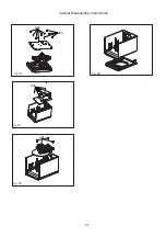
Page 24: ...8 2 Fig D3 Fig D5 Fig D4 Cabinet Disassembly Instructions Fig D6 A02 A03 A04 A02 ...
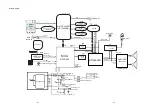
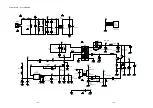
Page 28: ...Wiring Diagram Display Board Decoder Board AMP Board DVD Loader Power Board 11 1 11 1 ...
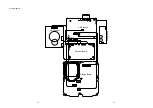
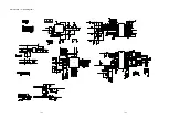
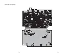
Page 31: ...AMP Board Layout Diagram 12 3 12 3 ...
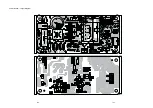
Page 33: ...Display Board Layout Diagram 12 5 12 5 ...
Page 35: ...Power Board Layout Diagram 12 7 12 7 ...
Page 42: ...Decoder Board Layout Diagram 12 14 12 14 ...
Page 44: ...Revision List Revision List Version 1 0 Initial Release 14 1 ...

