Mechanical Instructions
EN 9
LC4.41A AA
4.
4.2
Service Position
First, put the TV set in its service position. Therefore, place it
upside down on a table top (use a protection sheet or foam
bars).
4.2.1
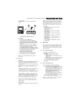
The Foam Bars
Figure 4-2 Foam bars
The foam bars (order code 3122 785 90580) can be used for
all types and sizes of Flat TVs. By laying the plasma TV flat on
the (ESD protective) foam bars, a stable situation is created to
perform measurements and alignments. By first placing a
mirror flat on the table under the TV you can easily see if
something is happening on the screen.
4.3
Assy/Panel Removal
4.3.1
Rear Cover
Warning:
Disconnect the mains power cord before you remove
the rear cover.
1.
Remove the screws that secure the rear cover.
2.
Lift the rear cover from the cabinet cautiously. Make sure
that wires and other internal components are not damaged
during cover removal.
4.3.2
Side I/O Panel
Figure 4-3 Side I/O panel
1.
Remove the rear panel.
2.
Remove the screw from the cable clip [1].
3.
Remove the screws [2] from the loudspeaker cabinet.
4.
Lift the loudspeaker cabinet from the frame.
5.
Disconnect the cable [3] from the panel.
6.
Remove the fixation screws [4], and slide the panel out of
its bracket.
4.3.3
LED Panel
Figure 4-4 LED panel
1.
Remove the rear panel.
2.
Disconnect the cable [1] from the panel.
3.
Remove the fixation screws [2].
4.
Remove the panel.
4.3.4
Keyboard Control Panel
Figure 4-5 Keyboard control panel
1.
Remove the rear panel.
2.
Remove the screws [1] from the loudspeaker cabinet.
3.
Lift the loudspeaker cabinet from the frame.
4.
Release the three fixation clamps [2] and pull the panel out
of the bracket.
5.
Disconnect the cable [3] from the panel.
E_06532_018.eps
170504
G_16240_012.eps
150206
2
1
4
3
4
G_16240_013.eps
170206
2
1
1
2
1
2
G_16240_014.eps
170206
2
3
1


