IC
Integrated Circuit
IF
Intermediate Frequency
Interlaced
Scan mode where two fields are used to form one frame. Each field contains
half the number of the total amount of lines. The fields are written in 'pairs',
causing line flicker.
IR
Infra Red
IRQ
Interrupt ReQuest
Last Status
The settings last chosen by the customer and read and stored in RAM or in the
NVM. They are called at start-up of the set to configure it according the cus-
tomers wishes
LCD
Liquid Crystal Display
LED
Light Emitting Diode
LINE-DRIVE Line drive signal
LVDS
Low Voltage Differential Signalling, data transmission system for high speed
and low EMI communication.
MPEG
Motion Pictures Experts Group
NVM
Non Volatile Memory: IC containing TV related data (for example, options)
OSD
On Screen Display
Progressive Scan
Scan mode where all scan lines are displayed in one frame at the same
time, creating a double vertical resolution.
RAM
Random Access Memory
RC
Remote Control transmitter
RC5
Remote Control system 5, the signal from the remote control receiver
RGB
Red, Green, and Blue. The primary colour signals for TV. By mixing
levels of R, G, and B, all colors (Y/C) are reproduced.
RGBHV
Red, Green, Blue, Horizontal sync, and Vertical sync
ROM
Read Only Memory
SAM
Service Alignment Mode
SIF
Sound Intermediate Frequency
SC
SandCastle: two-level pulse derived from sync signals
SCL
CLock Signal on I2C bus
SDA
DAta Signal on I2C bus
SDRAM
Synchronous DRAM
SIF
Sound Intermediate Frequency
STBY
STandBY
VGA
Video Graphics Array
XTAL
Quartz crystal
YPbPr
Component video (Y= Luminance, Pb/Pr= Colour difference signals)
Y/C
Luminance (Y) and Chrominance (C) signal
Y-OUT
Luminance-signal
Page 29
Summary of Contents for L05HD
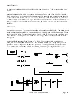
Page 13: ...FIGURE 5 TV SIGNAL PROCESSOR Page 11 ...
Page 16: ...FIGURE 7 CONTROL Page 14 ...
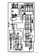
Page 19: ...FIGURE 9 DETAILED VIDEO SIGNAL FLOW BLOCK Page 17 ...
Page 24: ...FIGURE 13 AUDIO OUTPUT Page 22 ...
Page 27: ...FIGURE 16 WIRING INTERCONNECT Page 25 ...
Page 28: ...Page 26 SERVICE POSITION ...
Page 32: ......


