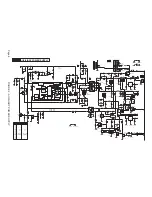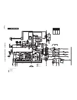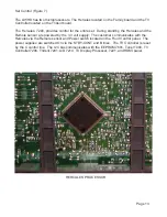
CRT panel (Figure 10)
RGB is fed to the CRT panel on connector 1331. The CRT panel for the L05HD has a single
chip CRT drive circuit. RGB is fed to 7330 on Pins 1, 2, and 3. Signal is output to the CRT
on Pins 7, 8, and 9. BC_INFO or Cutoff on Pin 5 is fed back to the TV Signal Processor on
the Trident panel. The IC is powered by a 200 volt supply on Pin 6.
DC operating voltages for the CRT panel are located on connector 1351. The Filament volt-
age is located on Pin 2. The 200VA voltage on Pin 5 powers 7330. The VBAT voltage on
Pin 3 and the +12V_LOT voltage on Pin 6 powers the SVM circuit.
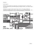
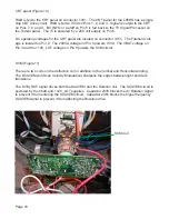
SVM (Figure 11)
There are two coils on the deflection coil in addition to the Vertical and Horizontal winding.
The SCAVEM coil (Scan Velocity Modulation) sharpens the edges between light and dark
transitions.
The SVM_ROT signal drives both the SCAVEM and the Rotation coil. The SCAVEM circuit is
powered by the Vbatt and +12V_LOT supplies. Capacitor 2376 blocks the dc Rotation signal
to prevent it from entering the SCAVEM circuit. Capacitor 2381 blocks the higher frequency
SCAVEM signal to prevent it from affecting the Rotation drive.
Page 18
SVM Coil
Summary of Contents for L05HD
Page 13: ...FIGURE 5 TV SIGNAL PROCESSOR Page 11 ...
Page 16: ...FIGURE 7 CONTROL Page 14 ...
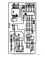
Page 19: ...FIGURE 9 DETAILED VIDEO SIGNAL FLOW BLOCK Page 17 ...
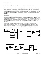
Page 24: ...FIGURE 13 AUDIO OUTPUT Page 22 ...
Page 27: ...FIGURE 16 WIRING INTERCONNECT Page 25 ...
Page 28: ...Page 26 SERVICE POSITION ...
Page 32: ......


