63
Repair Flow Chart
Go to cover page
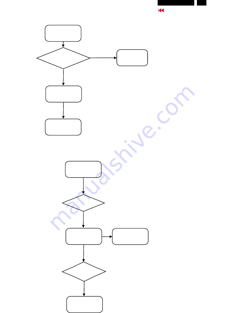
Bad brightness
Check
Inverter panel output
740~920Vrms
No
Yes
Bad Inverter
panel
Check fluorescent
lamp
Bad image
Check
Video,fh/fv
signals
Yes
Yes
Check LCD panel
No
No
Check LCD panel
Check
all connectors &
LVDS cable
No
Check main panel
Check components
cold soldering
Hudson2 200P3
Summary of Contents for Hudson2 200P3
Page 33: ...32 Hudson2 200P3 9 Go to cover page Schematic PWB Components side view ...
Page 34: ...9 Go to cover page 32 Hudson2 200P3 Schematic PWB Compohnents side view ...
Page 36: ...9 Go to cover page 33 Hudson2 200P3 Schematic PWB Copper track side view ...
Page 39: ...9 Go to cover page 36 Hudson2 200P3 Schematic diagram TMSD RX TMDS Transmitter ...
Page 40: ...37 9 Go to cover page Hudson2 200P3 Schematic diagram VIDEO Video Decoder ...
Page 45: ...9 Go to cover page 42 Hudson2 200P3 Schematic diagram POWER SUPPLY ...
Page 47: ...43 9 Go to cover page Hudson2 200P3 Power Board C B A copper track smc side view ...
Page 50: ...46 9 Go to cover page Hudson2 200P3 Schematic diagram AUDIO AMP MIC PREAMP ...
Page 51: ...9 Go to cover page 47 Hudson2 200P3 Schematic diagram AUDIO PWR KEYPAD ...
Page 54: ...9 Go to cover page 50 Hudson2 200P3 Inverter Diagram PWB AMBIT ...
Page 70: ...66 Hudson2 200P3 Go to cover page CA110 Application Continued ...


