12
OSD Lock/Unlock, Aging Mode
Go to cover page
ATTENTION
OSD MAIN CONTROLS LOCKED
ATTENTION
OSD MAIN CONTROLS UNLOCKED
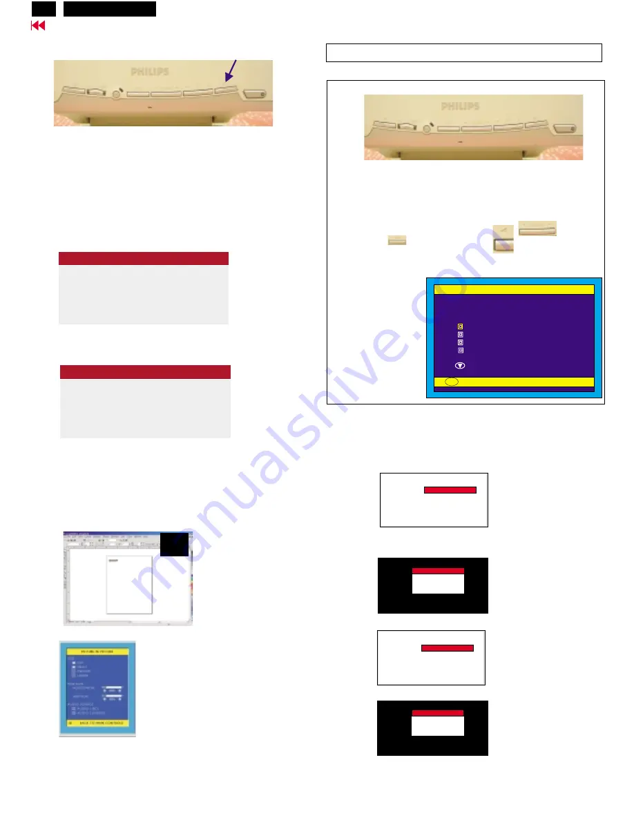
To Lock/Unlock OSD function (User Mode)
The OSD function can be locked by pressing "OK" button(1) for more
than 10 seconds, the screen shows following windows for 3 seconds.
Everytime when you press "AUTO" or "OK" button, this message
appears on the screen automatically.
Unlock OSD function:
Locked OSD function can be released by pressing"OK" button for
more than 10 seconds again.
PICTURE IN PICTURE (PIP):
Press the PIP hotkey on front control, will bring up PIP screen as
shown in Fig. 1.
Monitor (embeded software) will detect CVBS and S-Video input
for PIP function automatically at this moment.
Step 1:
Step 2:
When Factory mode comes on monitor screen, disconnect the
Signal Cable at this moment.
Access Factory Mode
Factory Mode:
How to Get into Factory Mode Menu
Turn on LCD monitor.
Push AUTO "
" & Left-VOLUME"
" buttons
simultaneously 3 seconds around.
Bring up Factory mode indication as shown in Fig 2.
Fig. 2
Fig. 1
---------->
AUTO
---------->
VOLUME
Factory Mode
CODE VERSION. 2.02 2002-08-07
CONFIG VERSION. 2.02 2002-08-07
OSD VERSION.
2.02 2002-08-07
ORIGINAL PANEL COLOR
9300K For CAD/CAM
6500K FOR IMAGE MANAGEMENT
AUTO COLOR ADJUST
EXIT MAIN CONTROLS
TO PROCESS ADJUSTING
OK
Factory Mode
indication===========>
Front control panel
1 = Buttons for the OSD menu (On-Screen-Display)
2 = Power indicator (PC)
3 = Power button
(OK button for OSD lock/unlock)
Fig. 1
Fig. 2
Fig. 3
Fig. 1
---------->
-------------->
---------->
------------>
---------->
AUTO
PIP
(OK)
1
2
3
Bring up
After 5 seconds, bring up :
After 5 seconds, bring up :
:
After 5 seconds, bring up :
----------
----------
repeatly
Connect signal cable again => go back to normal display.
Access Aging.. Mode
A G I N G MODE.......
A G I N G MODE.......
FACTORY MODE
A G I N G MODE.......
A G I N G MODE.......
FACTORY MODE
A G I N G MODE.......
A G I N G MODE.......
FACTORY MODE
A G I N G MODE.......
A G I N G MODE.......
FACTORY MODE
<---------- PIP
Hudson2 200P3
Summary of Contents for Hudson2 200P3
Page 33: ...32 Hudson2 200P3 9 Go to cover page Schematic PWB Components side view ...
Page 34: ...9 Go to cover page 32 Hudson2 200P3 Schematic PWB Compohnents side view ...
Page 36: ...9 Go to cover page 33 Hudson2 200P3 Schematic PWB Copper track side view ...
Page 39: ...9 Go to cover page 36 Hudson2 200P3 Schematic diagram TMSD RX TMDS Transmitter ...
Page 40: ...37 9 Go to cover page Hudson2 200P3 Schematic diagram VIDEO Video Decoder ...
Page 45: ...9 Go to cover page 42 Hudson2 200P3 Schematic diagram POWER SUPPLY ...
Page 47: ...43 9 Go to cover page Hudson2 200P3 Power Board C B A copper track smc side view ...
Page 50: ...46 9 Go to cover page Hudson2 200P3 Schematic diagram AUDIO AMP MIC PREAMP ...
Page 51: ...9 Go to cover page 47 Hudson2 200P3 Schematic diagram AUDIO PWR KEYPAD ...
Page 54: ...9 Go to cover page 50 Hudson2 200P3 Inverter Diagram PWB AMBIT ...
Page 70: ...66 Hudson2 200P3 Go to cover page CA110 Application Continued ...


