Mechanical Instructions
EN 9
FHP PDP
4.
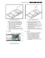
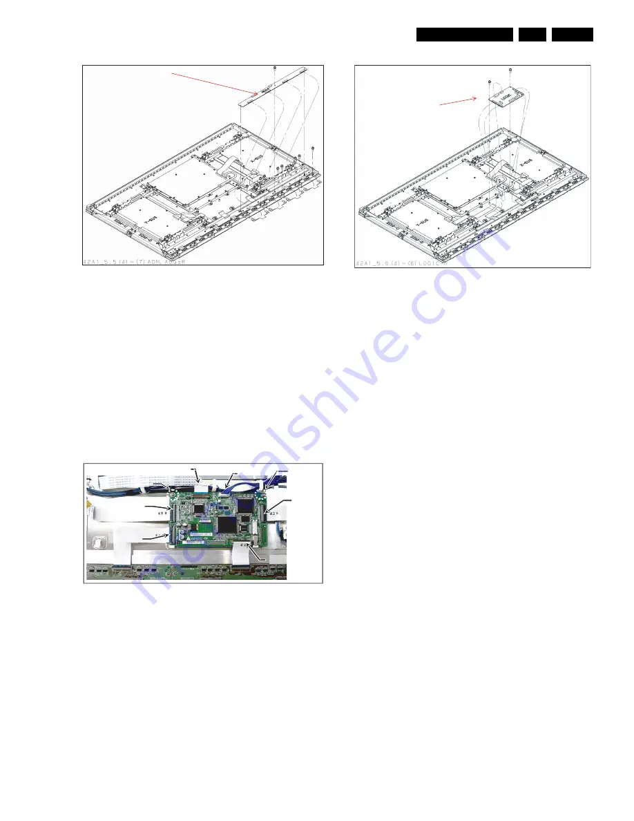
Figure 4-9 ABUS-R board removal (2)
Remove the circuit board by following the steps below. To
install the circuit board, reverse the removal procedure.
1.
Disconnect the connector CN42 on the ABUS-R board.
2.
Release the lock of the FPC connectors CN43, CN44,
CN45, CN46 and disconnect the ADM flexible board.
3.
Release the lock of the FPC connector CN41 and
disconnect the signal cable.
4.
Remove the screws (M3X8) fixing the ADM.
5.
Remove the screws (M3X8) fixing the ABUS-R board.
6.
Remove the ABUS-R board.
7.
When installing the ABUS-R board, put the board in such a
position that it is locked by the tabs before fixing it with the
screws.
4.1.6
Logic Board
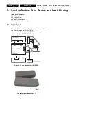
Figure 4-10 Logic board removal (1)
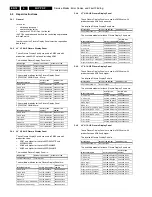
Figure 4-11 Logic board removal (2)
Remove the circuit board by following the steps below. To
install the circuit board, reverse the removal procedure.
1.
Disconnect the EH connector CN6.
2.
Release the lock of the FPC connectors CN2, CN3, CN4,
CN5 and disconnect the signal cable.
3.
Slide the lock of the FPC connector CN7 toward the PSU
board side, then gently push it down toward the front and
remove the PSU signal cable.
4.
Remove the screws (M3 X 8) fixing the Logic board.
5.
Remove the Logic board.
6.
When installing the Logic board, put the board in such a
position that it is locked by the tabs before fixing it with the
screws.
4.1.7
PSU Board
Remove the circuit board by following the steps below. To
install the circuit board, reverse the removal procedure.
1.
Release the lock of the large cable clamp.
2.
Disconnect the X-SUS board connector CN23.
3.
Disconnect the Y-SUS board connector CN33.
4.
Disconnect the ABUSR board connector CN42.
5.
Disconnect the ABUSL board connector CN52.
6.
Remove the wires from the small cable clamp.
7.
Disconnect the Logic board connector CN6.
8.
Disconnect the PSU signal cable from the PSU board with
connector CN69.
(6)
F_14582_013.eps
300905
(3)CN7
(4)
(1)CN6
(4)
(2)CN2
(2)CN3
(2)CN10
(2)CN9
F_14582_014eps
300905
(5)
F_14582_015.eps
300905


