Mechanical Instructions
EN 8
FHP PDP
4.
3.
Disconnect the connectors CN22, CN23 and CN26.
4.
Pull out the XSUS board horizontally and disconnect the
connectors (CN24, CN25).
5.
Remove the X-SUS board.
Make sure that you do not touch the heat sink when removing
the Y-SUS board.
4.1.3
Y-SUS Circuit Board
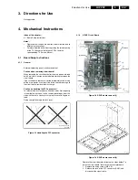
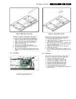
Figure 4-4 Y-SUS board removal (1)
Figure 4-5 YSUS board removal (2)
Remove the circuit board by following the steps below. To
install the circuit board, reverse the removal procedure.
1.
Remove the fixing screws (M3 X 8).
2.
Release the lock of the FPC connector CN31 and
disconnect the signal cable.
3.
Disconnect the connectors CN32, CN33.
4.
Pull out the YSUS board horizontally and disconnect the
connectors (CN34, CN35).
5.
Remove the Y-SUS board.
Make sure that you do not touch the heat sink when removing
the Y-SUS board.
4.1.4
ABUS-L Circuit Board
Figure 4-6 ABUS-L board removal (1)
Figure 4-7 ABUS-L board removal (2)
Remove the circuit board by following the steps below. To
install the circuit board, reverse the removal procedure.
1.
Disconnect the connector CN52 from the ABUS-L board.
2.
Release the lock of the FPC connectors CN53, CN54,
CN55 and CN56 and remove the ADM flexible board.
3.
Release the lock of the FPC connector CN51 and
disconnect the signal cable.
4.
Remove the screws (M3X8) fixing the ADM.
5.
Remove the screws (M3x8) fixing the ABUS-L board.
6.
Remove the ABUS-L board.
7.
When installing the ABUS L-board, put the board in such a
position that it is locked by the tabs before fixing it with the
screws.
4.1.5
ABUS-R Circuit Board
Figure 4-8 ABUS-R board removal (1)
(5)
(5)
(5)
(5)
(4)CN33
(5)
(4)CN32
(3)CN31
(1)
(1)
(1)
(6)
(6)
Pull out
(1)
(2)CN34
(2)CN35
F_14582_008.eps
071005
Pull out
(6)
F_14582_009.eps
300905
(3)CN51
(5)
(4)
(2)CN55
(4)
(2)CN54
(4)
(2)CN53
(4)
(4)
(4)
(4)
(4)
(6)
(6)
(1)CN52
(2)CN56
F_14582_010.eps
300905
(6)
F_14582_011.eps
300905
(3)CN41
(5)
(6)
(1)CN42
(6)
(4)
(2)CN46
(4)
(4)
(4)
(4)
(4)
(4)
(4)
(2)CN43
(2)CN44
(2)CN45
F_14582_012.eps
300905


