Service Modes, Error Codes and Fault Finding
EN 14
5.
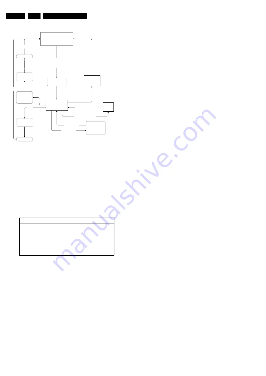
Figure 5-2 SAM Flowchart
How to enter
Use one of the following methods:
•
Use a standard RC-transmitter and key in the code 062596
directly followed by the OSD (i+) button
Note: the OSD (i+) is not available on the original FM242
remote control, therefore use another Philips remote
control (e.g. MG, EMG or A10).
•
Short jumpers 3 and 4 of connector 0382 on the SCAVIO
panel.
The following screen is visible:
Figure 5-3 SAM Menu 'General'
1.
Type Nr. Gives the commercial type number of the
monitor, e.g. 42FD9945/01.
2.
AG Code. Is not implemented.
3.
SW Version OTC (AAAAAB-X.Y-xxxxx).
Note: You will find details of the latest software versions in
the chapter 'Software Survey' of the 'Product Survey -
Colour Television' publication, which is published four
times each year.
•
A = the chassis name (FM23 for 32" displays or FM242
for 42" SDI-displays).
•
B = the region (E= Europe, A= Asia Pacific, U= NAFTA,
L= LATAM; in our case G = Global).
•
(if valid) C = the configuration name (B= Basic, E=
Enhanced; for PW & EPLD-software this will be named
B).
•
X = the main software version number.
•
Y = the sub software version number.
•
x = last five digits of 12nc code.
4.
SW Version PW (AAAABC-X.Y-xxxxx). See description
above.
5.
SW Version EPLD (AAAABC-X.Y-xxxxx). See description
above.
6.
Errors 1. Gives the last five errors of the error buffer. The
last detected error is displayed at the most left position.
The errors are displayed as 2 digit numbers and separated
by a space. When less than 10 errors occurred, the rest of
the line(s) is empty. In case of no errors the text 'No Errors'
is displayed behind menu item 'Errors 1'. See paragraph
5.5 for a description.
7.
Errors 2. Gives the first five errors of the error buffer. The
last detected error is displayed at the most left position.
8.
Operational hours. The Operations Hours indicate the
time that the display was active with half an hour resolution.
It represents the system hours (OTC), not the PDP hours.
9.
Reset error buffer. Erase the contents of the error buffer.
Press 'OK' on your remote control to activate. The content
of the error buffer is cleared.
10. Store. This will store the performed alignments. Press 'OK'
on your remote control to activate.
Note: if you do not want to store the performed alignments,
leave the SAM mode via code 00 on your remote control.
Do not activate the 'store' item.
How to navigate
Use one of the following methods:
•
Select the sub-menu's (upper line) with the CURSOR
LEFT/RIGHT keys on the remote control transmitter.
•
Select the menu items with the CURSOR UP/DOWN keys.
With the CURSOR LEFT/RIGHT keys it is possible to:
–
Activate the selected menu item.
–
Change the value of the selected menu item.
•
To toggle to the SDM mode, use the standard customer
RC-transmitter and key in the code 062596, directly
followed by the MENU key.
How to exit
Use one of the following methods:
•
Switch the set 'off' (with the Mains switch or by pulling the
Mains cord).
Note: new alignment settings are always stored, even
when item 'store' was not activated!
•
Switch the set to 'standby' by pressing the power button on
the remote control transmitter.
Note: new alignment settings are always stored, even
when item 'store' was not activated!
•
Use the standard RC-transmitter and key in the code 0 0.
Note: new alignment settings are not stored (except when
item 'store' was activated)!
5.2.3
Customer Service Mode (CSM)
Purpose
When a customer is having problems with his TV-set, he can
call his dealer or helpdesk. The service technician can than ask
the customer to activate the CSM, in order to identify the status
of the set. Now, the service technician can judge the severe
ness of the complaint. In many cases, he can advise the
customer how to solve the problem, or he can decide if it is
necessary to visit the customer.
The CSM is a read only mode, therefore modifications in this
mode are not possible.
"Standby"
Service Alignment Mode
Display "SAM" top level
menu
Ignore all "Service
unfriendly" modes
SDM
NORMAL OPERATION
SAM submenus
(whitepoints, align-
ments, etc.)
RC sequence "0-6-2-5-9-6-OSD "(for Europe & A/P)
or
RC sequence "0-6-2-5-9-6-INFO+" (for USA/LatAm)
or
Short SAM pins (works also from Standby)
RC-code "0-6-2-5-9-6-OSD"
or
RC-code "0-6-2-5-9-6-INFO+"
"UNDO" ignore
all "Service
unfriendly
modes"
RC sequence
"00"
STANDBY
OFF
(Settings made
during alignments
are stored)
Upper menu selection
(with cursor buttons)
RC button,
e.g. P+ or P-
RC-code "0-6-2-5-9-6-MENU" -
Lower menu selection
(with cursor buttons)
Mains OFF
Mains ON
Do not store
settings made
during alignments
RC button,
e.g. P+ or P-
Settings made
during alignments
are stored
STANDBY
CL 165320
99
_
101
260901
Service Alignment Menu
General
Type Nr. -
AG Code
42FD9945/01 **00 00
SW Version OTC
AAAAAB-X.Y_xxxxx
SW Version PW
AAAABC-X.Y_xxxxx
SW Version EPLD
AAAABC-X.Y_xxxxx
Errors 1
xx xx xx xx xx
Errors 2
xx xx xx xx xx
Operational hours
xx
Reset error buffer
Press OK to reset
Store
Press OK to store
CL 26532011_016.eps
200303
Summary of Contents for FM242
Page 7: ...Directions for Use EN 7 FM242 AA 3 3 Directions for Use ...
Page 8: ...Directions for Use EN 8 FM242 AA 3 ...
Page 9: ...Directions for Use EN 9 FM242 AA 3 ...
Page 31: ...Electrical Diagrams and PWB Layouts 31 FM242 AA 7 Audio Panel Supply Right High ...
Page 66: ...66 FM242 AA 7 Electrical Diagrams and PWB Layouts Personal Notes Personal Notes ...
Page 90: ...Revision List EN 90 FM242 AA 11 11 Revision List First release ...


