


Alignments
EN 84
EM5.2E AA
8.
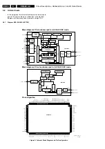
8.3.5
GEO-NOR (Normal Geometry)
Note:
Use for all geometry alignments an
external
pattern
generator with a geometry pattern (e.g. crosshatch).
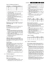
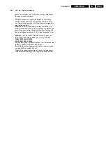
Figure 8-3 Geometry Alignments
Service tip:
When the set is equipped with a rotation coil, use
this menu item to check its correct alignment. If alignment is not
correct, go to the INSTALLATION menu, choose SETUP,
press OK, and choose PICTURE TILT. With the use of a
crosshatch test pattern, align it to a correct horizontal picture.
V. SLOPE
Align the zero crossing of the frame deflection to the
mechanical middle of the picture tube.
1.
First, set the start conditions for 16:9 sets according to the
table “Vertical S-Correction default value”. Position the
boundary-stripes of the test pattern on the edges of the
picture tube.
2.
Align V. SLOPE (during alignment, the lower half of the
picture is blanked) such, that the middle line of the test
pattern is matched with the edge of the pattern transient in
the middle of the picture.
3.
Repeat the alignment if necessary.
Table 8-4 Vertical S-Correction default value
V. SHIFT AND V. AMPLITUDE (vertical alignment)
Align the vertical centre and height of the picture.
1.
Use V. AMPLITUDE to align the vertical amplitude so that
the entire test pattern is visible.
2.
Set V. SHIFT to value "32".
3.
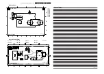
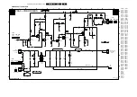
Connect a voltmeter (V_dc) between R3624 and "hot"
ground.
4.
Adjust the DC voltage to
"0"
with potmeter R3642 (see
figure 8-1).
5.
Use V. SHIFT again to align the test pattern roughly
vertically in the middle.
6.
Repeat the alignment if necessary.
V. S-CORRECTION
Align for equal blocks on top, middle, and bottom of the picture
tube.
Align V. S-CORRECTION such that a block at the top (or
bottom) of the picture has the same height as a block in the
middle of the picture.
H. SHIFT AND H. AMPLITUDE (horizontal alignment)
1.
Use H. AMPLITUDE to align the horizontal amplitude so
that the entire test pattern is visible.
2.
Use H. SHIFT to align the picture horizontally in the middle.
3.
Repeat the H. AMPLITUDE alignment if necessary.
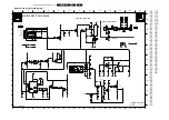
Note:
In case the horizontal linearity in wide-screen mode is
out of tolerance, add a "DC-shift correction" panel (3104 328
06230) to connector 1419 of the DAF-panel [diagram I]. On the
DC-shift panel, cut diode
6433
for correction to the right or
diode
6432
for correction to the left.
Caution: Be sure to switch "OFF" the set first.
Never
plug
in a not pre-aligned module in a playing set!
EAST/WEST ALIGNMENT
1.
Use EAST/WEST PARABOLA to align the vertical lines
until straight.
2.
Use UPPER EAST/WEST CORNER to align the vertical
lines in the upper corners until straight.
3.
Use LOWER EAST/WEST CORNER to align the vertical
lines in the lower corners until straight.
4.
Use EAST/WEST TRAPEZIUM to align for a rectangular.
5.
Use HORIZONTAL BOW to correct the E/W parabola
such, that it becomes symmetrical.
6.
Use HORIZONTAL PARALLELOGRAM to align for straight
vertical lines if necessary.
Repeat steps 1 to 6 if necessary.
E_06532_010.eps
110204
1
2
3
4
5
6
7
8
9
10
11
12
VERT. SLOPE
VERT. SHIFT
VERT. AMPLITUDE
V.S-CORRECTION
HOR. SHIFT
HOR. AMPLITUDE
E/W PARABOLE
UPPER E/W CORNER
LOWER E/W CORNER
E/W TRAPEZIUM
HOR. PARALLELOGRAM
HOR. BOW
Picture Tube
V. S-Correction default value
28" RF 16:9 Mk2
16
29" RF 4:3
32
32" RF 16:9
16
32" RF 16:9 Bleeder
16
32" RF 16:9 EMEC
27
32" RF 16:9 DOD-2
20


