


Service Modes, Error Codes, and Fault Finding
EN 18
EM5.2E AA
5.
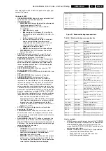
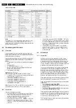
Table 5-3 Error table.
Note:
Error codes 1, 6, or 18 are protection codes and in this case,
supplies of some circuits will be switched "OFF". Also, in
protection, the LED will blink the number of times equivalent to
the most recent error code.
5.6
The Blinking LED Procedure
5.6.1
Introduction
Via this procedure, you can make the contents of the error
buffer visible via the front LED. This is especially useful for fault
finding, when there is no picture.
When the SDM is entered, the front LED will show (blink) the
contents of the error-buffer. Error-codes = 10 are shown as
follows:
•
A long blink of 750 ms (which is an indication of the decimal
digit),
•
A pause of 1.5 s,
•
"n" short blinks (where "n" = 1 - 9),
•
When all the error-codes are displayed, the sequence
finishes with a LED blink of 3 s,
•
The sequence starts again.
Example:
Error 12 9 6 0 0.
After activation of the SDM, the red front LED will show:
•
1 long blink of 750 ms (which is an indication of the decimal
digit) followed by a pause of 1.5 s,
•
2 short blinks followed by a pause of 3 s,
•
9 short blinks followed by a pause of 3 s,
•
6 short blinks followed by a pause of 3 s,
•
1 long blink of 3 s to finish the sequence,
•
The sequence starts again.
Note:
If errors 1, 6 or 18 occur, the LED always gives the last
occurred error even if the set is NOT in service mode.
5.6.2
How to Enter
Use one of the following methods:
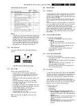
•
Enter the SDM (only via soldering pads marked "SDM" on
SSB). The blinking red front LED will show the entire
contents of the error buffer (this works in "normal
operation" mode and in "protection" mode).
•
Transmit the commands "MUTE" -
"062500"
- "OK" with a
normal RC. The complete error buffer is shown. Take
notice that it takes some seconds before the blinking led
LED starts.
•
Transmit the commands "MUTE" -
"06250x"
- "OK" with a
normal RC (where "x" is a number between 1 and 5). When
x= 1 the last detected error is shown, x= 2 the second last
error, etc.... Take notice that it takes some seconds before
the blinking led LED starts.
•
"DIAGNOSE X" with the DST (where "x" is a number
between 1 and 5). When x= 1 the last detected error is
shown, x= 2 the second last error, etc.... When x = 0 all
errors are shown.
5.7
Protections
5.7.1
Introduction
This chassis has only one microprocessor (OTC), which
remains active during Standby. This because power of the
microprocessor and the attached memory chip set is coming
from the 3V3 supply, which is derived from the 5V Standby-
circuitry. Therefore, in both Power-on as in Standby mode, the
microprocessor is connected to this power supply.
If a fault situation is detected, an error code will be generated
and if necessary, the set is put in protection mode. The
protection mode is indicated by the blinking of the front LED at
a frequency of 3 Hz (or by a coded blinking in special cases).
In some error cases however, the microprocessor does not put
the set in the protection mode (this is the case with the -
hardware - loudspeaker protection of the audio amplifier).
The content of the error buffer can be read via the service menu
(SAM), the blinking LED procedure or via DST/ComPair.
To get a quick diagnosis, this chassis has three service-modes
implemented:
•
The
Customer Service Mode (CSM).
•
The
Service Default Mode (SDM).
Start-up of the set in a
predefined way.
•
The
Service Alignment Mode (SAM).
In this mode, items
of the set can be adjusted via a menu.
You can enter both SDM and SAM modes via the 'service pads'
on the SSB, via an RC-transmitter (DST or standard RC), or via
ComPair. It is not possible to enter the SAM in "standby"; the
TV has to be in "normal operation" mode.
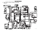
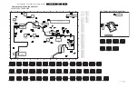
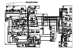
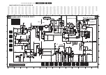
The "Protection Diagram" shows the structure of the protection
system. See diagram below.
Error Device
Description
Def. item
Defect. module indication
Diagram
1
M24C32
NVM, spontaneous blinking error 1
7011
Control
B5a
2
Hfail Protection
Horizontal Flyback protection
/
Horizontal Flyback
/
3
SAA4978
PICNIC
7713
Feature Box
B3a
4
Supply 5V
5V protection
/
+5V Supply
B5a
5
Supply 8V
8V protection
/
+8V Supply
B5a
6
Slow I
2
C bus blocked
Spontaneous blinking error 6
/
Slow I
2
C Blocked
/
7
TDA9330
HOP High-end Output Processor
7301
Video Controller
B4
8
TDA932x
HIP High-end Input Processor
7323
Chroma IF IO
B2
12
TDA9178
Topic
7302
Video Controller
B4
13
UV1318/...
Tuner protection
1200
Tuner
A8
14
MSPxxxx
ITT sound processor
7651
Audio module
B6a
16
FBX
Feature Box Protection
/
+3V (Fbx) Supply
B3
18
Fast I
2
C bus blocked
Spontaneous blinking error 18
/
Fast I
2
C Blocked
/
26
SAA4998
FEM
7760
+3V (Fbx) Supply
B3b
27
T6TX5EF
Eagle
7724
+3V (Fbx) Supply
B3c
28
Black current loop
Black current loop
/
Video Controller
/
32
M29W400BT
Flash Ram (EPG)
7012
EPG Memory
B5a