


Service Modes, Error Codes and Fault Finding
GB 30
EM3E
5.
The content of the error buffer can be read via the service
menu (SAM), the blinking LED procedure or via DST/
ComPair.
The DST/ComPair ‘diagnose’ functionality will force the set
into the ‘Service Standby’, which is alike the usual Standby,
however the microprocessor remains completely in normal
operation.
To get a quick diagnosis the EM3E has 3 service-modes
implemented:
•
The Customer Service Mode (CSM).
•
The Service Default Mode (SDM). Start-up of the set in a
predefined way.
•
The Service Alignment Mode (SAM). In this mode items
of the set can be adjusted via a menu and with the help
of test patterns.
Both SDM & SAM modes can be entered via the 'service
pads' on the SSB (see Figure 4-7), via an RC-transmitter
(DST or standard RC) or via ComPair. It is not possible to
enter the SAM in Standby, the set has to be in ‘normal
operation’ mode.
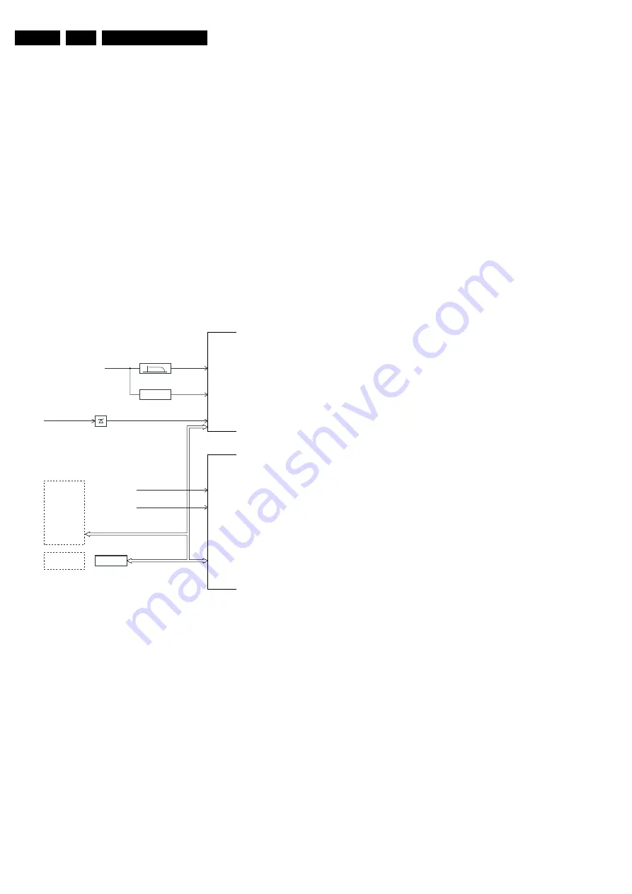
The EM3E 'Protection Diagram' shows the structure of the
protection system. See diagram below.
Figure 5-10
There are several types of protections:
•
I
2
C related protections.
•
OTC related protections (via polling on I/O pins or via
algorithms).
•
HOP related protections (mainly for deflection items).
•
Hardware errors that are not sensed by the OTC (e.g.
BRIDGECOIL_PROT, NON_VFB, ARC_PROT).
All protections are explained below.
5.7.2
I
2
C Related Protections
In normal operation, some registers of the I
2
C controlled ICs
are refreshed every 200 ms. During this sequence, the I
2
C
busses and the I
2
C ICs are checked.
An I
2
C protection will take place if the SDA and SCL lines are
short-circuited to ground, or to each other. An I
2
C error will
also occur, if the power supply of the IC is missing (e.g.
FBX_PROT (error 16)).
5.7.3
OTC Related Protections
If a protection is detected at an OTC input, the OTC will start
to scan all protection inputs every 200 ms for 5 times. If the
protection on one of the inputs is still active after 1 s, the
m
P
will put the set in the protection mode. Before the scanning
is started, a so called ‘ESD refresh’ is carried out. This is
done, because the interrupt on one of the inputs is possibly
caused either by a flash or by ESD. As a flash or ESD can
influence IC settings, the HOP, HIP, MSP, PICNIC, NVM and
Tuner are initialised again, to ensure the normal picture and
sound conditions of the set.
8 V and 5 V protection: The
m
P senses the presence of the
8 V and 5 V (via the ‘+5V_CON’ and ‘+8V_CON’ lines). If one
(or both) of these voltages is (are) not present, an error code
is stored in the error buffer of the NVM, and the set is put in
the protection mode.
5.7.4
HOP Related Protections
Every 200 ms, the status register of the HOP is read by the
OTC (via the I
2
C bus). If a protection signal is detected on
one of the inputs of the HOP, the relevant error bit in the HOP
register is set to ‘high’. If this error bit is still ‘high’ after 1 s,
the OTC will store the error code in the error buffer of the
NVM and, depending on the relevancy of the error bit, the set
will either go into the protection mode or not.
The following protections are implemented:
•
HFB (Horizontal Flyback): If the horizontal flyback is
not present, this is detected via the HOP (HFB_X-
RAY_PROT). One status bit is set to ‘high’. The error
code is stored in the error buffer and the set will go into
the protection mode.
•
Flash detection: When a flash is detected via the EHT-
info line (via D6303 and T7303), the H-drive (and so the
Line output stage) is stopped immediately. The FLS-bit in
the HOP status register is set to ‘high’. As the duration of
a flash is very short, the FLS-bit is re-set to ‘low’ again
after the flash refresh, and via a ‘slow start’ the set will
start again.
5.7.5
Hardware Related Protections
Due to the architecture (with 'hot' deflection) there are some
protections that can not be sensed by the microprocessor.
Three of these protections will lead to a protection on set
level (Standby mode and blinking LED), while another will
only lead to a circuit protection.
TV-set Protection
The following fault conditions will lead to a ‘complete’ set
protection:
•
BRIDGECOIL protection: This is sensed via the ‘EW’
signal going to the base of TS7652 (via R3495 and
D6499). In a normal situation, the voltage on C2498
(diagram A4) is high, TS7652 is conducting. When bridge
coil 5422 (diagram A3) is short circuited, the voltage on
C2498 changes to low, which will block TS7652. In this
case, also TS7641 will block and the voltage on 2642 will
rise until TS7443 is forced in conduction. The ‘SUP-
ENABLE’ signal (in normal operating condition -20 V) is
shorted now to ground level, which will force the Main
Power Supply to Standby mode.
•
ARC protection: If there are ‘open’ connections (e.g.
bad solder joints) in the
high energy
deflection circuitry,
this can lead to damaging effects (read: fire). For that
reason, the E/W current is sensed (via 3479//3480). If
this current becomes too high, the ‘thyristor’ circuit
(TS7653 and TS7654) is triggered. TS7442 is switched
‘on’ and TS7443 is forced into conduction. . The ‘SUP-
ENABLE’ signal is shorted now to ground level, which will
force the Main Power Supply to Standby mode.
XPR (43)
7301
7001
FLS (5)
HFB-XRAY-PROT
HOP
+8V SENSE (105)
+5V SENSE (106)
OTC
EHT-info
HFB
+5V_CON
+8V_CON
Flash detect
I2C
I2C PROTECTIONS
HIP
HOP
PICNIC
TUNER
NVM
DNR
MSP
TOPIC
I2C
I2C
PICNIC 3V3
FBX
PROTECTION
CL 16532044_024.eps
090501
www.freeservicemanuals.info
Summary of Contents for EM3E
Page 96: ...Electrical Diagrams and PWB s 65 EM3E 7 SSB LOT Side Part 1 B27 www freeservicemanuals info ...
Page 97: ...66 EM3E 7 Electrical Diagrams and PWB s SSB LOT Side Part 2 B27 www freeservicemanuals info ...
Page 98: ...Electrical Diagrams and PWB s 67 EM3E 7 SSB LOT Side Part 3 B3 B5 www freeservicemanuals info ...
Page 118: ...www freeservicemanuals info ...
Page 119: ...www freeservicemanuals info ...
Page 120: ...www freeservicemanuals info ...